Advertisement
Safety messages used in this document

Risk of injury and damage. Ignoring warnings can cause personal injury and/or damage to products and other property.

Risk of malfunctions. Ignoring cautions can cause the product to not operate as intended.
Note
Important information to the section in the manual.
Uponor uses safety messages in the document to indicate special precautions required for the installation and operation of any Uponor product.
System description
Always use the specified combination of heating blanket and pipe dimension.
Never use a heating blanket (i.e. 160 mm) for a smaller pipe dimension (i.e. d =125 mm). It will overheat the pipe and damage the pipe surface.
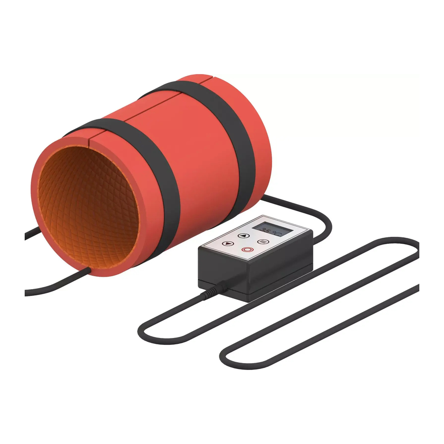
The Uponor Ecoflex heating blanket can heat up the Uponor Ecoflex pipe ends to soften them for the fitting installation.
The Uponor Ecoflex heating blanket set contains:
- a controller with a large LCD display
- a flexible heating blanket, available for the pipe dimensions 125 mm, 140 mm or 160 mm
Uponor supplies one set per dimension. The heating blankets are hard-wired to the controller.
Components
Controller

Main characteristics:
- Large, illuminated LCD display
- Membrane keypad, easy to operate
- Cycle timer with user selectable, delayed start
Heating blanket

Main characteristics:
- Flexible and lightweight
- Fixing straps with hook-and-loop-fastener
- Even heating
- Moisture and chemical resistant
- VDE approved
Operation
Power On/Off
Note
The temperature controller does not have an On/Off-switch.
Pressing the standby key will do following:
- put the controller into standby mode
- turn off the display backlight
- stop the temperature control function
Controller settings

| Item | Description |
| A | Up key |
| B | Down key |
| C | Menu key |
| D | Standby key |
Adjust all controller settings with the membrane keypad on the front panel.
Main screen

| Item | Description |
| A | Temperature sensor |
| B | Temperature display in °C |
| C1 | Heating mode on |
| C2 | Heating mode off |
The main screen shows the actual temperature of the sensor inside the heating blanket.
Set-point temperature

| Item | Description |
| A | Indicator for set-point mode |
| B | Set-point temperature |
| C | Set-point temperature in °C |
To adjust the set-point temperature, change to the set-point screen:
- Press and hold the up/down key for 2 seconds, while the display shows the main screen, until "SET-POINT" appears on it.
- Use the up/ down key to adjust the required temperature.
- Press and hold the up/ down key for approximately 5 seconds to return to the main screen and to see the current process temperature.
Settings menu
Note
If no key is pressed for at least 10 seconds while the controller is in one of the setting menus, the display will return to the main screen.

| Item | Description |
| A | Timer settings |
| B | Hysteresis settings |
| C | Offset settings |
| D | Unit settings |
| E | Indicator for active setting |
| F | Hysteresis value (1... 9) |
| G | Offset value (-10... +10) |
| H | Temperature unit in °C |
To move the setting indicator (little arrow) to each menu item in turn, press the menu key subsequently. If the menu key is pressed while the arrow points to the "Units" option, the controller will return to the main screen.
When the up/ down key is pressed while the settings menu is active, the item the arrow points to can be edited.
Timer settings

| Item | Description |
| A | Timer hours (hh) and minutes (mm) |
| B | Indicator for active setting |
| C | "Timer hold" |
| D | "Timer en" |
| E | Setting enabled |
| F | Setting disabled |
Timer hold
Note
If "hold" is selected the timer will not start until the temperature set point is reached. If "hold" is unselected the timer will begin as soon as the controller returns to run mode.
To use the "Timer hold" function obey the following steps:
- Press the menu key to move the arrow to the "hold" box.
- To activate or inactivate the "Timer hold" function use the up/ down keys.
Timer enabled
Note
Always activate "Timer en" when you want to use the "Timer hold" function!
Note
If "Timer en" is selected while "Timer hold" is unselected the countdown will start even if the set point temperature is not reached yet.

To use the "Timer en" function obey the following steps:
- Press the menu key to move the arrow to the "en" box.
- To activate or inactivate the "Timer en" function use the up/ down keys.
The timer period is displayed in the top left corner of the main screen while the timer is enabled. If "Timer hold" and "Timer en" are enabled at the same time the display will show a "h" next to the timer until the countdown starts.
After the timer countdown has ended the heating mode is turned off automatically and the controller is going back to standby mode.
In both modes the colon between the hours and the minutes will flash to indicate that the timer is running.
Timer completed
After the countdown stops, following things will happen simultaneously:
- The temperature control function will stop.
- The display will start to flash and show "Timer Complete!".
Timer restart

To restart the timer or to revert to standard mode, press the menu key from the "Timer Complete!" screen.
The "RESTART TIMER" option will start the heating cycle with the same settings as before.
The "REVERT TO STANDARD MODE" option will reset the settings from the cycle before and the controller will return to standard mode.
To change between both options, press the up/ down key. Enter each option by pressing the menu key.
Hysteresis
Note
Selecting a lower value for the hysteresis will give a better accuracy for the set-point temperature, but the heater will be turned on and off more often. This can reduce the life time of the relay. If accuracy is less important it is recommended to use a higher value.

The hysteresis is the difference (in degrees) between switch-on and switch-off temperature during the heating mode.
The heat up period will stop at the set-point temperature. It will be switched on again at the set-point temperature minus the hysteresis value. The hysteresis range is adjustable between 1 and 9. The default value is 5.
While the arrow on the display points to the Hysteresis option, use the up/ down keys to change the value.
Offset value
Note
In some situations the actual temperature of the product being heated may differ due to higher or lower heat losses.
The offset value is used to correct the difference between the temperature displayed and the actual temperature of the product being heated. This difference can occur because the sensor of the controller is attached directly to the heater.
The offset value can be adjusted between -10 and +10, but the value required can only be found by testing in the given situation.
While the arrow on the display points to the offset option, use the up/ down keys to change the value.
Unit settings
While the arrow on the display points to the units option, use the up/ down keys to change the setting between °C (Celsius) and °F (Fahrenheit).
Pressing the menu key at this point will return the controller to the main screen.
Standby
Pressing the standby key for 2 seconds will put the controller into standby mode. The display will show "STANDBY".
The temperature control function will stop and the display backlight goes dark.
Pressing the standby key while the controller is in standby mode will turn the backlight on again and the controller will return to the main screen.
Display contrast
While the controller is in standby mode the contrast of the display can be changed using the up/ down keys.
Technical data
Technical specifications
| Controller | |
| Description | Value |
| Product classification | Class 2 |
| Power supply | 90 - 230 V AC, 50 - 60 Hz supply |
| Supply current | 100 mA |
| Relay current max. | 100 Amps |
| Temperature control range | 0... 300°C |
| Temperature measurement range | -18... +350°C |
| Temperature accuracy | ±0,5... ±1° |
| IP (Ingress Protection) rate | IP 62 |
| Heating blanket | |
| Description | Value |
| Thickness | 1,5 - 2,2 mm |
| Temperature range | -60... 250°C |
| IP (Ingress Protection) rate | IP 64 |
Dimensions

All measurements are given in mm.
Safety instructions
Safety measures
Note
For safe and proper use, obey the instructions given in this document. Keep them for future reference.
The installer and operator agree to comply with following measures regarding Uponor products:
- Read and obey the instructions and processes in the document.
- The installation must be performed by a qualified installer in accordance with local regulations.
- Uponor is not liable for modifications not specified in this document.
- Switch off all connected power supplies before starting any wiring work.
- Do not expose the Uponor components to flammable vapours or gases.
- Do not use water to clean electrical Uponor products/ components.
Uponor is not liable for damage caused by ignoring the instructions in this document or the applicable building code.
Power
Uponor system power supply: 230 V AC, 50 Hz
In case of emergency, immediately disconnect the power.
Technical constraints
To avoid interference, keep data cables away from components bearing power of more than 50 V.
Uponor GmbH
Industriestraße 56,
D-97437 Hassfurt, Germany
www.uponor.com

Documents / Resources
References
Download manual
Here you can download full pdf version of manual, it may contain additional safety instructions, warranty information, FCC rules, etc.
Advertisement


Need help?
Do you have a question about the Ecoflex and is the answer not in the manual?
Questions and answers