Table of Contents
Advertisement
Quick Links
Advertisement
Table of Contents

Subscribe to Our Youtube Channel
Related Manuals for Okofen S158 EN 2.1


Summary of Contents for Okofen S158 EN 2.1
- Page 1 Installation manual Weighing System Storage Tank ENGLISH S158 EN...
- Page 2 Title: Installation manual Weighing System Storage Tank Article number: S158 EN 2.1 Version valid from: 02/2021 Approved: Christian Wohlinger Author ÖkoFEN Forschungs- & EntwicklungsgesmbH A-4133 Niederkappel, Gewerbepark 1 Tel.: +43 (0) 72 86 / 74 50 Fax.: +43 (0) 72 86 / 74 50 – 210 E-Mail: oekofen@pelletsheizung.at...
-
Page 3: Table Of Contents
Contents Contents 1 Dear Customer 2 Types of safety warning sign 3 Product Description Function conditions 4 Installation of the Weighing System Installation of the weighing cells Installation of the dummy weighing cells 5 Connection of the Weighing System Electrical connection of the weighing system Settings in the boiler controller... -
Page 4: Dear Customer
1 Dear Customer Dear Customer Proficiency, innovation and quality combined. This is the tradition on which ÖkoFEN shapes the future. We are very pleased that you too have decided to purchase a product from ÖkoFEN. This manual is intended to help you operate the product safely, properly and eco- •... -
Page 5: Types Of Safety Warning Sign
2 Types of safety warning sign Types of safety warning sign The warning signs use the following symbols and texts. Types of safety warning sign Risk of injury Consequences of risk Avoiding risk DANGER Danger - indicates a situation that could lead to death or lifethreatening injury. WARNING Warning - indicates a situation that could lead life-threatening or serious injury. -
Page 6: Product Description
3 Product Description Product Description Weighing cells measure the weight of fuel in the FleXILO storage tank to within +/- 100 kg and up to a maximum weight of 7 tonnes. The threshold value, the minimum weight for a warning message, can be varied. The warning message appears on the operating device and disappears when the filling weight is above the set minimum weight. -
Page 7: Installation Of The Weighing System
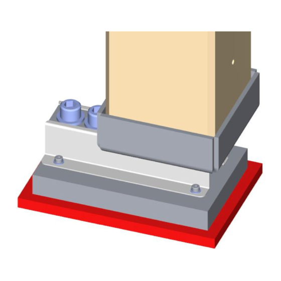
4 Installation of the Weighing System Installation of the Weighing System Description of the installation steps for the weighing system. The description of the installation of the storage tank can be found in the Storage Tank Installation Manual. Only fit the weigh cells and dummy weighing cells after the Flexilo is fully assembled and positioned. -
Page 8: Connection Of The Weighing System
5 Connection of the Weighing System Connection of the Weighing System DANGER Electric shock hazard! The electrical connection may only be carried out by an authorised electrician. ▶ Disconnect the power supply from the complete heating system before working on the pellet boiler. Electrical connection of the weighing system Electrical connection of FA Cable routing, connection of the distribution box to the weighing circuit board (meas-... - Page 9 5 Connection of the Weighing System Electrical connection of CMP 0.6 Cable routing, connection of the distribution box to the weighing circuit board (meas- uring transducer), connection to the boiler controller CMP 0.6 and power supply. The wires from the load cell to the distribution may not be extended! Ensure correct polarity for the signal cables when connecting.
- Page 10 5 Connection of the Weighing System Electrical connection of CMP 1.4 Cable routing, connection of the distribution box to the weighing circuit board (meas- uring transducer), connection to the boiler controller CMP 1.4 and power supply. The wires from the load cell to the distribution may not be extended! Ensure correct polarity for the signal cables when connecting.
- Page 11 5 Connection of the Weighing System 1. Connection of the weighing cell measuring signal red (signal –) white (signal +) grey and black (GND) blue and green (0–10 Volt) 2. Connection of the measuring signal to the Boiler controller The polarity of the measuring signal connection must correspond to the following diagram: The terminal of the circuit board furthest from the marking X3 is always terminal...
-
Page 12: Settings In The Boiler Controller
5 Connection of the Weighing System Settings in the boiler controller Pelletronic Plus Parameter Display/default value Description P 233 Activation of the level detection system 1 = Level detection system for storage tank P 132 Current weight Display of the current weight in the storage tank. P 134 low.
Need help?
Do you have a question about the S158 EN 2.1 and is the answer not in the manual?
Questions and answers