
Related Manuals for Pylon Technologies RT12100G31


Summary of Contents for Pylon Technologies RT12100G31
- Page 1 LFP Lithium Ion Battery System RT12100G31 Operation Manual Information Version:1.0 21P1RT0701...
-
Page 2: Table Of Contents
Please read this manual beforeinstall the battery and follow the instruction carefully during the installation process. Any confusion, please contact Pylontech immediately for advice and clarification. Symbol in label, manual and product Safety Precautions Before Connecting In Using Introduction Features Specification Panel Equipment interface instruction... -
Page 3: Symbol In Label, Manual And Product
1. Symbol in label, manual and product Do not reverse connection the positive and negative. Do not place near open flame Do not place at the children and pet touchable area. Caution! Warning! Reminding. Safety related information. Risk of battery system failure or life cycle reduces. Keep away from strong magnetic field. -
Page 4: Safety Precautions
Label for Waste Electrical and Electronic Equipment (WEEE) Directive (2006/66/EC) and its amendments The certificate label for Bluetooth SIG The Bluetooth Certification Mark for Janpanese market. The TUV Mark certificate label for Safety Testing (EN62619) by TÜV Rheinland The cTUVus Mark certificate label for Safety Testing (UL1973) and Functional Safety (IEC60730-1/UL60730-1) by TÜV Rheinland 2. -
Page 5: Before Connecting
6) Do not connect power terminal reversely. 7) All the battery terminals must be disconnected for maintenance 8) Please contact the supplier within 24 hours if there is something abnormal. 9) Do not use cleaning solvents to clean battery 10) Do not expose battery to flammable or harsh chemicals or vapors 11) Do not paint any part of battery, include any internal or external components 12) Do not connect battery with PV solar wiring directly... -
Page 6: In Using
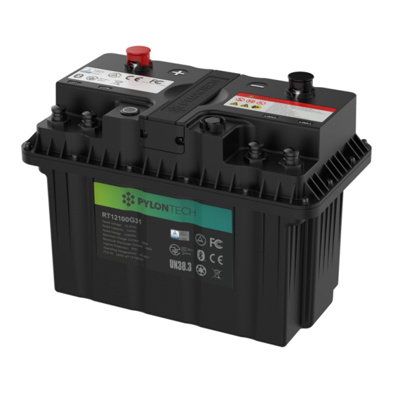
3. Introduction RT12100G31 is a lithium iron phosphate battery module used to replace the typical lead-acid battery. The battery can be charged by solar power, diesel generator, and utility power via relevant AC/DC converter. The battery can be used for energy storage and providing back-up power for typical electrical appliances. -
Page 7: Features
3.1 Features 1) Products with strong environmental adaptability, structural reliability and electrical reliability, able to adapt to the harsh automotive environment. 2) Robust power performance. Available for 1C-rate continuous operation and upto 2C-rate instantaneous discharge. 3) Support both serial and parallel connections. Up to 16 batteries (max. 4 groups in serial) can be connected together per single system. -
Page 8: Specification
3.2 Specification RT12100G31 Battery Dimension... - Page 9 Basic Parameters Value Nominal Voltage (V) 12.8 Nominal Capacity (Ah) 325(L)*173.5(W)*226(H) Dimension (mm) Weight (Kg) ±0.2 10.8~14.4 Discharge Voltage Range (Vdc) Recommended Charge Voltage (Vdc) 14 ~ 14.4 Recommend Charge/Discharge Current (A) Max. Continue Charge/Discharge Current (A) Peak Discharge Current (A) 200@30sec 500Kbps, 115200bps...
-
Page 10: Panel
3.3 Panel RT12100G31 Panel Description 3.4 Equipment interface instruction Power Button Power button pressed: ready to turn on. Power button pops back: power off. For storage or shipping. LED Status Indicators: Power on/Normal Flash 1, OFF 1.5S, on 0.5s Flash 2,OFF 1s, on 1s,... - Page 11 External Communication Interface (Dry contact and COM port) Dry Contact IN1+ IN1- IN2+ CANH COM1 CANL IN2- RS485A COM2 RS485B PIN Assignments Front View of Cable Dry Contact Definition: Pin1 Input, passive signal. Close: Enable Heater function. Open Disable Heater function Pin2 Pin3 Input, passive signal.
- Page 12 Notes: 1.Input signals should be passive signals 2.The voltage value of output signal is less than 25V, and the current value is less than 10mA. CAN(COM) 500 Kbps. 120Ω terminal resistance. RS485/Console(COM) For manufacturer or professional engineer to debug or service. Default Communication speed 115200 bps.
-
Page 13: Safe Handling Guide
4. Safe handling guide 4.1 Schematic diagram of solution... -
Page 14: Danger Label
4.2 Danger label... -
Page 15: Tools
4.3 Tools Wire cutter Screwdriver NOTE Use properly insulated tools to prevent accidental electric shock or short circuits. If insulated tools are not available, cover the entire exposed metal surfaces of the available tools, except their tips, with electrical tape. 4.4 Safety gear It is recommended to wear the following safety gear when dealing with the battery pack... -
Page 16: Installation And Operation
5. Installation and operation 5.1 General guidance All batteries must be connected in parallel before series connection. Please make sure the modules are having less than 0.1Vdc voltage difference between each other, or ideally fully charge the modules in parallel, before connecting them in serial to avoid capacity imbalance. -
Page 17: Package Items
otherwise it will affect the Bluetooth signal strength. When multiple batteries are connected in series or parallel, it is possible to work without connecting the communication cable between the batteries to an upper controller but it is required to connect the internal communication cable in order to ensure the consistency of SOC and better performance of the batteries. - Page 18 b. 1 set of internal communication cable Length(M) Description Internal Communication For internal serial connection between Cable batteries Pin assignment Link 0 Link 1 3 ~ 8 is pin - pin 1 set of Dry contactor heater terminal Description Dry Contact After power on the system, insert into the I/O port on the Heater master battery, the heater feature will be enabled to...
- Page 19 Spare Description communication Empty comm. terminal acting as spare part or further insert terminal comm. cable to connect to upper controller. 2) For External cable kits: NOTE External Cable Kit, NOT include in battery carton box. It`s acting as an option for customer to purchase relevant power/comm. cable to connect to the inverter.
- Page 20 Power cable Length(M) Power Cable Positive 4AWG, WI0PRT121266 WI0PRT121267 WI0PRT121268 WI0PRT121269 (Orange) GT25-8 Negative Terminals WI0PRT121262 WI0PRT121263 WI0PRT121264 WI0PRT121265 (Black) b. Internal Communication cable Length(M) Internal Communication cable CAT6,Black, WI0SRT121254 WI0SRT121255 WI0SRT121256 WI0SRT121257 2*ALTW M12 Connector...
-
Page 21: Installation Location
External Communication cable Length(M) External Communication Cable CAT6,Black, WI0SRT121258 WI0SRT121259 WI0SRT121260 WI0SRT121261 ALTW M12 Connector 5.3 Installation location Make sure that the installation location meets the following conditions: The floor is flat and level. There are no flammable or explosive materials. The ambient temperature is within the range from -40°C to 60°C. -
Page 22: Installation Method Of Multiple Batteries
Caution If the ambient temperature is out of the operating range, the battery stops operating to protect itself. The optimal temperature range for the battery pack to operate is 10°C to 40°C. Frequent exposure to harsh temperatures may deteriorate the performance and life of the battery. 5.4 Installation method of multiple batteries The battery can be placed flexibly according to the actual site environment. - Page 23 Series Configration Recommended Charge Discharge Voltage Voltage Value (Vdc) Range (Vdc) 14 ~ 14.4 10.8 ~ 14.4 28 ~ 28.5 22~ 28.5 42~ 43 33 ~ 43 56 ~ 57 44 ~ 57 Parallel Configuration Maximum Charge /Discharge Current Value 1~8P 100A*N ( N= module amount, 1~8) 9P~16P...
- Page 24 Diagram of battery communication cable connection: Diagram of battery communication cable connection: The internal communication port LINK0 of the 1st battery remains in EMPTY, and LINK1 is connected to the 2nd battery's internal communication port LINK0. All the way connected to the last module`s LINK0. The batteries are numbered sequentially and the last battery's internal communication port LINK1 is remain in EMPTY.
- Page 25 5.5 Production and adjustment of communication plugs 1) The communication plug can be flexibly adjusted to the direction of actual placement of the battery during installation, follow below procedure. and sockets with the Navigation key (1) and insert the Align the plugs plugs.
-
Page 26: Power On
Caution 1) follow local electric safety and installation policy, a suitable breaker between battery system and inverter could be required. 2) all the installation and operation must follow local electric standard. 5.6 Power on Double check all the power cable and communication cable. empty Link Port 0 is the Master Battery Module, others are 1) The one with... - Page 27 4) If require enable heater feature, insert the Dry contact heater terminal into the I/O port of the Master Battery only. Description Dry Contact After power on the system, insert into the I/O port on the Heater master battery, the heater feature will be enabled to Terminal automatically function when necessary Note:...
-
Page 28: Power Off
5.7 Power off 1) Turn external power source off. 2) When the slave is in the switch-closed state, the master module can control the switch status of all batteries. When the master is switched off, other batteries will go into sleep mode (in sleep mode self-consumption at 100uA). - Page 29 the component inside the module. Contact your local distributor for further help. Symptom: The switch button pops up and the battery still has output. Possible condition: If the battery can still communicate or the indicator light flashes normally, Switch button cannot be disconnected, switch failure. Contact your local distributor for further help.
- Page 30 (2) Follow the "single device power down" problem to investigate. Cascade device address assignment Symptom: The indicator flashes (1s on and 1s off) or via close-loop communication, the host computer indicates address assignment failure Inspection steps: (1) first check whether the number of cascade units exceeds 16pcs - product design only supports a maximum of 16 cascade units.
- Page 31 (2) Read the battery's history records to check whether the first unit is in the under-voltage protection state before the connection is interrupted or the first unit is offline and the under-voltage protection state exists before it is offline - the first unit will notify all devices to enter hibernation after the under-voltage protection, or the first unit will notify all devices to enter hibernation forcibly when it monitors the under-voltage protection state before other devices are...
-
Page 32: Emergency Situations
8. Emergency Situations 1) Leaking Batteries If the battery pack leaks electrolyte, avoid contact with the leaking liquid or gas. If one is exposed to the leaked substance, immediately perform the actions described below. Inhalation: Evacuate the contaminated area and seek medical attention. -
Page 33: Remarks
9. Remarks Recycle and disposal In case a battery (normal condition or damaged) needs disposal or needs recycling, it shall follow the local recycling regulation (i.e. Regulation (EC) Nº 1013/2006 among European Union) to process, and using the best available techniques to achieve a relevant recycling efficiency. - Page 35 Pylon Technologies Co., Ltd. No. 73, Lane 887, ZuChongzhi Road, Zhangjiang Hi-Tech Park Pudong, Shanghai 201203, China T+86-21-51317699 | +86-21-51317698 service@pylontech.com.cn www.pylontech.com.cn...
Need help?
Do you have a question about the RT12100G31 and is the answer not in the manual?
Questions and answers