Table of Contents
Advertisement
Quick Links
Digital-to-Synchro/Resolver
PCI Express Card
Hardware Manual
DDC's PCIe card provides ideal compatibility with modern desktop computers, retaining high performance
accuracy with six independent channels each.
Applications
•
High Performance Industrial and Military Position
Feedback and Control Systems
•
Motor Control
•
Machine Tool Control
•
Antenna Control
•
Robotics and Process Control Systems
For more information: www.ddc-web.com/SB-3623XKX
© 2011 Data Device Corporation. All trademarks are the property of their respective owners.
Need a Custom Solution? DDC can customize designs for all
controllers, ranging from simple modifications of standard
products to fully customized solutions for commercial, military,
aerospace, and industrial applications.
Connectivity Power Control
Model: SB-3623XKX
Advertisement
Table of Contents

Subscribe to Our Youtube Channel
Related Manuals for DDC SB-3623XKX


Summary of Contents for DDC SB-3623XKX
- Page 1 Digital-to-Synchro/Resolver PCI Express Card Connectivity Power Control Hardware Manual Model: SB-3623XKX DDC's PCIe card provides ideal compatibility with modern desktop computers, retaining high performance accuracy with six independent channels each. Applications • High Performance Industrial and Military Position Feedback and Control Systems •...
- Page 2 Synchro/Resolver Synchro, Resolver, LVDT, RVDT, Inductosyn, MR, and Hall Conversion Solutions Since introducing the first synchro converter module in 1968, DDC has taken a leadership role in the design and manu- facture of modern data conversion products. DDC offers a complete line of Synchro/Resolver instrument-grade cards and test equipment including angle position indication and simulation, plus a variety of hardware and software to meet today’s civil, military, and COTS/MOTS...
- Page 3 Tel: (631) 567-5600, Fax: (631) 567-7358 World Wide Web - http://www.ddc-web.com For Technical Support - 1-800-DDC-5757 ext. 7771 United Kingdom - Tel: +44-(0)1635-811140, Fax: +44-(0)1635-32264 France - Tel: +33-(0)1-41-16-3424, Fax: +33-(0)1-41-16-3425 Germany - Tel: +49-(0)89-15 00 12-11, Fax: +49-(0)89-15 00 12-22...
- Page 4 Rev F February, 2019 20-25 Removed sections 5, 6, 7, and 8. ii, 10,18, all Minor edits, P2 mating connector part #s added, Rev G April, 2019 pages footer’s fixed Data Device Corporation SB-36230KX Manual www.ddc-web.com Rev G – 4/19...
-
Page 5: Table Of Contents
4.1 Digital to Synchro / Resolver Channels ..............13 4.2 On-board Reference Sine Oscillator ................16 4.3 Device Pinouts ......................18 SOFTWARE ....................... 23 5.1 Software Overview ....................23 ORDERING INFORMATION ................25 Data Device Corporation SB-36230KX Manual www.ddc-web.com Rev G – 4/19... - Page 6 L I S T O F F I G U R E S Figure 1. SB-3623XKX Synchro / Resolver PCI Express Output Card ........4 Figure 2. SB-36230KX Block Diagram ..................5 Figure 3. SB-36230KX Mechanical Outline ................6 Figure 4. Supplemental Power Connector Location ..............11 Figure 5.
- Page 7 Table 5. Reference Oscillator Options ..................16 Table 6. Oscillator Frequency ....................17 Table 7. Oscillator Amplitude ..................... 17 Table 8. DDC Supplied Mating Connectors ................18 Table 9. P3 Connector Pinouts ....................20 Table 10. P4 Connector Pinouts ....................22 Table 11.
-
Page 8: Preface
This section will define the text formatting used in the rest of the manual Text Usage • BOLD–indicates important information and table, figure, and chapter references. • BOLD ITALIC–designates DDC Part Numbers. • Courier New–indicates code examples. • <…> - indicates user-entered text or commands. Standard Definitions... -
Page 9: Supporting Documentation
1-631-567-5758 to the attention of Motion Feedback Technologies Applications DDC Website: www.ddc-web.com/ContactUs/TechSupport.aspx Please note that the latest revisions of Software and Documentation are available for download at DDC’s Web Site, www.ddc-web.com. Data Device Corporation SB-36230KX Manual www.ddc-web.com Rev G – 4/19... -
Page 10: Overview
0 to 26 Vrms (360 Hz to 11 kHz) o 0 to 115 Vrms (360 Hz to 1 kHz) Up to 60 mA output drive (with 0-11.8V ordering option) Transformer isolated Data Device Corporation SB-36230KX Manual www.ddc-web.com Rev G – 4/19... -
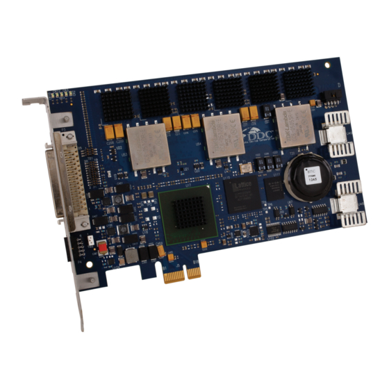
Page 11: Figure 1. Sb-3623Xkx Synchro / Resolver Pci Express Output Card
• Minimizes user application development effort - Windows Graphical User Interface (GUI) o User-friendly application that demonstrates full capabilities of the device Figure 1. SB-3623XKX Synchro / Resolver PCI Express Output Card Data Device Corporation SB-36230KX Manual www.ddc-web.com Rev G – 4/19... -
Page 12: System Requirements
Synchros and resolvers are used in applications where position feedback information is required. Providing accurate position information to simulate synchro/resolver outputs is essential to evaluate overall system performance. The SB- 36230KX is ideal for test stands and simulators. Data Device Corporation SB-36230KX Manual www.ddc-web.com Rev G – 4/19... -
Page 13: Mechanical Outline
O V E R V I E W Mechanical Outline Figure 3. SB-36230KX Mechanical Outline Data Device Corporation SB-36230KX Manual www.ddc-web.com Rev G – 4/19... -
Page 14: Specifications
99.5 kΩ differential kΩ Common-mode Range 15 / 50 (includes peak Reference signal) Option (SB-36232KX) Carrier Frequency Type Differential Voltage (Nominal) Vrms single ended kΩ differential 1.39 MΩ Data Device Corporation SB-36230KX Manual www.ddc-web.com Rev G – 4/19... - Page 15 6 Ch full load with ext. reference 6 Ch full load with int. oscillator (Full load) THERMAL Device Operating Temperature °C Storage Temperature °C FORM FACTOR/SPECIFICATION Standard height, Half length PCI Express x1 Data Device Corporation SB-36230KX Manual www.ddc-web.com Rev G – 4/19...
- Page 16 DC offset voltages will degrade accuracy if a DC reference is applied. LOR and frequency detection will indicate a fault with a DC reference. A dual-width slot is required for the 90V transformer isolated output option. Data Device Corporation SB-36230KX Manual www.ddc-web.com Rev G – 4/19...
-
Page 17: Hardware Installation
ATX/EPS/etc. specifications. This cable is also known as the “4 pin Molex power cable” and is used to power PATA hard drives, PATA optical drives, etc. These connectors are keyed and can only go in one way. Data Device Corporation SB-36230KX Manual www.ddc-web.com Rev G – 4/19... -
Page 18: Sb-3623X Led Status
Each channel can be configured for either Synchro, Differential Resolver, or Single- Ended Resolver outputs. See Table 2 below for the different signal connections. Refer to Table 9 for the connector pinout. Data Device Corporation SB-36230KX Manual www.ddc-web.com Rev G – 4/19... -
Page 19: Table 2. Signal Connections
Note: When using single-ended configurations, S1 and S4 on the card’s connector are disabled. Use associated analog ground on the card’s connector per output channel as a return to ground for outputs S2(Cos) and S3(Sin). Data Device Corporation SB-36230KX Manual www.ddc-web.com Rev G – 4/19... -
Page 20: Detailed Architecture
The output voltage for each channel is determined by the reference input voltage and transformation ratio. The transformation ratio is software programmable. See Table 3 for the different output voltage configurations. The output voltage configuration is programmable using the Set_D2rsChOutput() function. Data Device Corporation SB-36230KX Manual www.ddc-web.com Rev G – 4/19... -
Page 21: Table 3. Output Voltage Configurations
Two speed allows resolutions greater than 16 bits to be achieved. Refer to the Two- Speed Application Note (AN/MFT-10), the RD/RDC Applications Manual (MN- 19220XX-001) and the Synchro/Resolver Conversion Handbook. These documents are available at www.ddc-web.com. 4.1.5 Self Test The device has a built-in self test capability which uses an internal DC reference to exercise all channels and indicates a pass or fail status for each channel. - Page 22 Once this occurs, a power cycle to the computer will be necessary to restore all channels. Each DC-to-DC converter’s active status is monitored in a register accessible through software. See the Get_D2rsRefStatus() function for details. Data Device Corporation SB-36230KX Manual www.ddc-web.com Rev G – 4/19...
-
Page 23: On-Board Reference Sine Oscillator
Resolution Resolution SB-36231KX 360 Hz – 10 kHz 3.78 Hz 0 – 26 Vrms 8.4 mV SB-36232KX 360 Hz – 1 kHz 3.78 Hz 0 – 115 Vrms 37 mV Data Device Corporation SB-36230KX Manual www.ddc-web.com Rev G – 4/19... -
Page 24: Table 6. Oscillator Frequency
The programmed rotation speed corresponds to a frequency of the AC output waveform, and results in a time-varying voltage waveform. For detailed information on the setup, see Application Note AN/MFT13, available for download at www.ddc-web.com. Data Device Corporation SB-36230KX Manual www.ddc-web.com... -
Page 25: Device Pinouts
D E T A I L E D A R C H I T E C T U R E Figure 5. Simulation Board used as a Sine Reference Oscillator Block Diagram Device Pinouts This section delineates the user’s pinouts for the SB-3623XKX. The connectors described here are the two connectors on the I/O bracket. 4.3.1 I/O Connector Overview The supplied mating connectors are listed in Table 8 below. -
Page 26: Figure 6. P3 Mating Connector
D E T A I L E D A R C H I T E C T U R E Figure 6. P3 Mating Connector Figure 7. P4 Mating Connector Data Device Corporation SB-36230KX Manual www.ddc-web.com Rev G – 4/19... -
Page 27: Table 9. P3 Connector Pinouts
Internal reference oscillator output low (respective to RH) CH5_RH_IN Channel 5 – Reference excitation input high CH5_RL_IN Channel 5 – Reference excitation input low (respective to RH) CH3_RH_IN Channel 3 – Reference excitation input high Data Device Corporation SB-36230KX Manual www.ddc-web.com Rev G – 4/19... - Page 28 Channel 1 – Synchro/Resolver outputs. Refer to Table 2 for signal connections. CH1_S3_OUT CH1_S4_OUT Notes: All AGND and DGND pins are internally common. The inputs and outputs for unpopulated channels are No Connects. Data Device Corporation SB-36230KX Manual www.ddc-web.com Rev G – 4/19...
-
Page 29: Table 10. P4 Connector Pinouts
Sync pulse (channel 3) DGND Digital Ground Factory test point. Do not connect. DGND Digital Ground Notes: All DGND pins are internally common. The outputs for unpopulated channels are No Connects. Data Device Corporation SB-36230KX Manual www.ddc-web.com Rev G – 4/19... -
Page 30: Software
API works with the hardware. Table 11 shows a summary of the supported operating systems. Preli minar y The SB-36030Sx Software Manual can be downloaded from the DDC web site at www.ddc-web.com. Table 11. Motion Feedback Library C SDK Part Number Descriptions... - Page 31 The card is supplied with the SB-36030SL Motion Feedback LabVIEW support package. This software development kit includes a runtime library that provides the user with a hardware abstraction layer for the DDC Motion Feedback hardware in a LabVIEW environment. The Package includes 3 layers of VIs which enable easy application development.
-
Page 32: Ordering Information
- 1 – 10-pin Receptacle (2 mm pitch) - 10 – Crimp Terminals (2 mm pitch) - Synchro/Resolver software CD INCLUDED SOFTWARE (Available on SB-3623 Product Page at www.ddc-web.com) SB-36030SX- Motion Feedback C Software Development Kit (SDK) Operation System: 0 = Windows... - Page 33 Certifications Data Device Corporation is ISO 9001:2008, AS 9100 Rev C, EN 9100, and JIS Q9100 certified. DDC has been granted certification by the Defense Logistics Agency, Land & Maritime (DLA) for manufacturing Class D, G, H, and K hybrid products in accordance with MIL-PRF-38534.
- Page 34 Tel: 91 80 46797 0368 The first choice for more than 50 years! DDC is a world leader in the design and manufacture of high-reliability Connectivity, Power and Control solutions (Data Networking Components to Processor Based Subsystems, Space Qualified SBCs & Radiation Hardened Components;...
Need help?
Do you have a question about the SB-3623XKX and is the answer not in the manual?
Questions and answers