Advertisement
IMPORTANT: Read Safety Rules and Instructions carefully
Warning:
This unit is equipped with an internal combustion engine and should not be used on or near any unimproved forest-covered,
brush-covered or grass-covered land unless the engine's exhaust system is equipped with a spark arrester meeting applicable local or state
laws (if any). If a spark arrester is used, it should be maintained in effective working order by the operator. In the State of California the
above is required by law (Section 4442 of the California Public Resources Code). Other states may have similar laws. Federal laws apply
on federal lands. A spark arrester for the muffler is available through your nearest engine authorized service dealer or contact the service
department, P.O. Box 361131 Cleveland, Ohio 44136-0019.
PRINTED IN U.S.A.
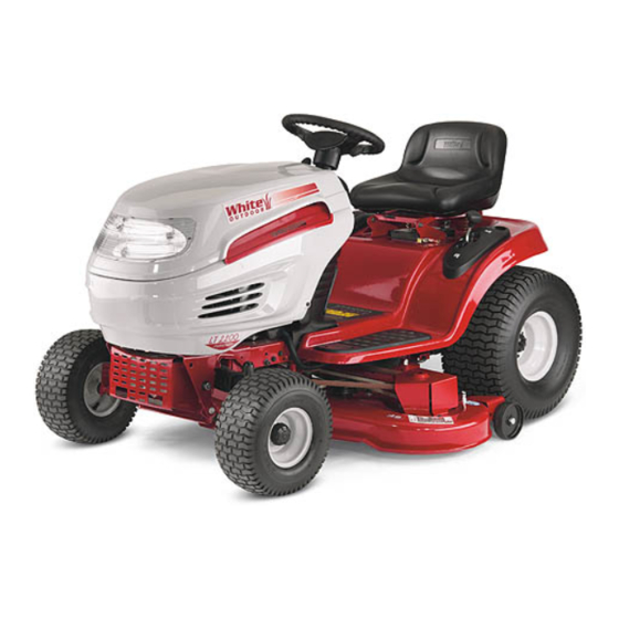
Operator's Manual
MTD LLC, P.O. Box 361131 Cleveland, Ohio 44136-0019
AutoCruise
™
Lawn Tractor
Model LT-2200
(13A6606H790)
FORM NO. 769-00983
(11/2003)
Advertisement

Subscribe to Our Youtube Channel
Related Manuals for White Outdoor AutoCruise LT-2200


Summary of Contents for White Outdoor AutoCruise LT-2200
- Page 1 Operator’s Manual AutoCruise ™ Lawn Tractor Model LT-2200 (13A6606H790) IMPORTANT: Read Safety Rules and Instructions carefully Warning: This unit is equipped with an internal combustion engine and should not be used on or near any unimproved forest-covered, brush-covered or grass-covered land unless the engine’s exhaust system is equipped with a spark arrester meeting applicable local or state laws (if any).
-
Page 2: Table Of Contents
TABLE OF CONTENTS Content Page Content Page Customer Support Maintenance Important Safe Operation Practices Service Tractor Set-Up Attachments & Accessories Operation Illustrated Parts List Making Adjustments Warranty Back Cover * Engine manual is included after the Illustrated Parts List in this manual. FINDING MODEL NUMBER This Operator’s Manual is an important part of your new lawn tractor. -
Page 3: Important Safe Operation Practices
SECTION 1: IMPORTANT SAFE OPERATION PRACTICES WARNING: This symbol points out important safety instructions which, if not followed, could endanger the personal safety and/or property of yourself and others. Read and follow all instructions in this manual before attempting to operate this machine. Failure to comply with these instructions may result in personal injury. - Page 4 27. Use only accessories and attachments approved for this Do not tow heavy pull behind attachments (e.g. loaded machine by the machine manufacturer. Read, dump cart, lawn roller, etc.) on slopes greater than 5 understand and follow all instructions provided with the degrees.
- Page 5 Never fill containers inside a vehicle or on a truck serviced professionally by your White Outdoor dealer. or trailer bed with a plastic liner. Always place Check brake operation frequently as it is subjected to containers on the ground away from your vehicle wear during normal operation.
- Page 6 SECTION 2: SLOPE GAUGE...
-
Page 7: Tractor Set-Up
SECTION 3: TRACTOR SET-UP Attaching the Battery Cables NOTE: If these cables are already attached, ignore these four steps and proceed to “Gas and Oil Fill-Up.” The positive battery terminal is marked Pos. IMPORTANT: (+). The negative battery terminal is marked Neg. (–). 1. -
Page 8: Operation
SECTION 4: OPERATION Know the Controls Read this owner’s manual and safety rules before operating your lawn mower. Compare figure below with your lawn tractor to learn about the loction and purpose of various controls and adjustments. Save this manual for future reference. - Page 9 Throttle Control Lever Choke Position The throttle control lever controls the speed of the engine. When set in a Fast given position, the throttle will maintain a uniform engine speed. Position Choke Control When pushed all the way forward, the throttle control lever also controls the choke.
- Page 10 WARNING: Never move the key into the Start position while the engine is running. Doing so may cause damage to your engine’s starter. Systems Indicator Monitor / Hour Meter Battery Light Oil Light Your tractor is equipped with four indicator lights and an hour meter as shown in the figure here.
- Page 11 AVOID SERIOUS INJURY OR DEATH and the PTO is disengaged. If this system should ever malfunction, do not operate the tractor, immediately contact a White Outdoor dealer. • GO UP AND DOWN SLOPES, NOT ACROSS. • AVOID SUDDEN TURNS. •...
- Page 12 Avoid stopping when driving up a slope. If it is necessary to stop while driving up a slope, start up smoothly and carefully to reduce the possibility of flipping the tractor over backward. Mowing This tractor is equipped with one of White Outdoor’s high quality cutting decks. The following information will be helpful when using the cutting deck with your tractor.
-
Page 13: Making Adjustments
WARNING: To help avoid blade contact or a thrown object injury, keep bystanders, helpers, children and pets at least 75 feet from the machine while it is in operation. Stop machine if anyone enters the area. • Do not mow at high ground speed, especially if a mulch kit or grass collector is installed. •... - Page 14 2. In front of the axle, measure the distance horizontally from the inside of the left rim to the inside of the right rim. Note the distance. 3. Behind the axle, measure the distance horizontally from inside of the left rim to the inside of the right rim. Note the distance.
- Page 15 Parking Brake Adjustment Hex Nut WARNING: Never attempt to adjust the brakes while the engine is running. Always disengage PTO, move shift lever into neutral position, stop engine and remove key to prevent unintended starting. If the tractor does not come to a complete stop when the brake pedal is completely depressed, or if the tractor’s rear wheels can roll with the parking brake applied, the Set gap...
- Page 16 Changing Engine Oil Oil Fill Cap Protective Cap Oil Drain Hose 1. Unscrew oil fill cap and remove dipstick from the oil fill tube. See Figure 9. 2. Pop open the protective cap on the end of the oil drain valve to expose the oil drain port.
-
Page 17: Service
SECTION 7: SERVICE WARNING: Before servicing, repairing, or inspecting, always disengage PTO, move shift lever into neutral position, set parking brake, stop engine and remove key from tractor to prevent unintended starting. Tire Pressure Never exceed the maximum inflation pressure shown on the sidewall of the tire. IMPORTANT: •... - Page 18 Jump-Starting Do not jump-start a damaged battery. Before connecting the jumper cables, make sure that the two IMPORTANT: equipment are not in contact and their ignitions are turned off. Follow the sequence described below very closely. 1. Connect the positive (+) lead of the jumper cable to the positive (+) post of the discharged battery. 2.
- Page 19 1. Remove the deck from beneath the tractor, then gently flip the deck over to expose its underside. Hex Flange Nut 2. Place a block of wood between the center deck Wood Block housing baffle and the cutting blade to act as a stabilizer.
- Page 20 WARNING: Shut tractor engine off, remove ignition key, disconnect the spark plug wire(s) and ground against the engine before proceeding with job. The V-belts on your tractor are specially designed to engage and disengage safely. A substitute (non- IMPORTANT: OEM) V-belt can be dangerous by not disengaging completely. For a proper working machine, use factory approved belts.
- Page 21 4. Remove the rear idler pulley from the double-idler successfully complete it. Otherwise, see your bracket while unrouting the belt from around both white outdoor dealer . the rear and the front idler pulley. See Figure 14. 5. Remove the hex bolt from the center of the engine 2.
-
Page 22: Attachments & Accessories
Extinguish cigarettes, cigars, pipes, and other sources of ignition prior to draining fuel. • Follow instructions in the Seasonal Storage section of the White Outdoor Engine Operator’s Manual for proper engine care prior to storing your tractor. •... - Page 23 SECTION 8: TROUBLESHOOTING Trouble Possible Cause(s) Corrective Action Engine fails to start PTO engaged. Disengage the PTO knob. Parking brake not engaged. Engage parking brake. Spark plug wire(s) disconnected. Connect wire(s) to spark plug. Throttle control lever not in correct Place throttle lever to CHOKE position.
- Page 24 SECTION 9: PARTS LIST FOR LT-2200 (Part of #26) 1 19...
- Page 25 Model LT-2200 Ref. Part Ref. Part Description Description 710-3015 Hex Cap Screw, 1/4-20 x .75 631-04035A Dash Panel, 4-style w/ Cargo Net 710-0599 Self-tapping Screw, 1/4-20 x .5 731-04214 Parking Brake Button 712-0324 Lock Nut, 1/4-20 731-1857 Throttle Control Lever 710-0895 Self-tapping Screw, 1/4-15 x .75 731-04213...
- Page 26 Model LT-2200...
- Page 27 Model LT-2200 Ref. Part Description Ref. Part Description 747-1130B Deck Stabilizer Rod 731-1990 Lift Lever Cover 683-0197B Lift Shaft Assembly 731-1993 Cover w/ Cup Holder 711-0332 Clevis Pin, .5 x .78 736-3078 Flat Washer, .349 x 1.0 x .063 712-3083 Lock Nut, 1/2-13 783-0677 Lift Adjustment Bracket...
- Page 28 Model LT-2200...
- Page 29 Model LT-2200 Ref. Part Ref. Part Description Description 719-0525C Pivot Bar: Axle 683-04004 RH Axle Assembly, .750 Diameter 710-0604A Self-tapping Screw, 16-18 x .625 683-0128A Steel Pivot Bar 783-0726B RH Pivot Support Bracket 712-0130 Lock Nut, 3/8-16 783-0727A LH Pivot Support Bracket 714-0162 Cotter Pin 783-0728...
- Page 30 Model LT-2200 IMPORTANT: For a proper working machine, use Factory Approved Parts. V-belts are designed to engage and disengage safely. A substitute (non OEM) V-belt can be dangerous by not disengaging completely.
- Page 31 Model LT-2200 Ref. Part Ref. Part Description Description 17840 Mounting Bracket 683-0266 Drive Pedal Assembly 618-04133 Drive Assembly 710-0650 TT Screw 5/16-18 x 0.875 618-04147 Variable Spd. Pulley Assembly 710-0726 AB Screw 5/16-12 x 0.75 3A 656-0059B Var. Spd. Pulley 710-1260A LD Screw 5/16-18 x 0.75 3B 683-04129...
- Page 32 Model LT-2200...
- Page 33 Model LT-2200 Ref. Part Description 732-0614 Ring, Wire 716-0231 Ring, E Type, .750 736-0336 Flat Washer, 5/8 x 1.0 x .030* 736-0337 Flat Washer, 5/8 x 1.0 x .040* 736-0349 Flat Washer, 5/8 x 1.0 x .020* 736-0335 Washer, Thrust .635 x 1.26 x .06 710-1325 Self-Tapping Screw, 1/4-20 x 1.625 719-04017...
- Page 34 Model LT-2200 Ref. Part No. Description 710-0227 AB Screw #8-18 x 0.5 710-0599 TT Screw 1/4-20 x 0.5 710-0726 AB Screw 5/16-12 x 0.5 710-1314A Socket Hd Scr 5/16-18 x .750 710-1315 TT Screw 3/8-16 x 1.25 712-0271 Sems Nut 712-3017 Hex Nut 3/8-16 721-0331...
- Page 35 Model LT-2200 SYSTEMS INDICATOR MONITOR YEL/WHT ORG/BLK...
- Page 36 Model LT-2200 25 14...
- Page 37 Model LT-2200: 46” Deck Ref. Part No. Description Ref. Part No. Description 618-04137 Pulley-Spindle Assembly 736-0760 Lock Washer 683-0254 Deck Hanger Bracket Assembly 737-04003B Nozzle 683-04104 Deck Assembly w/ Nozzle 737-3007 Grease 710-0347 Hex Bolt 3/8-16 x 1.75 738-0372B Shoulder Spacer 710-0514 Hex Bolt 3/8-16 x 1.0 738-0373...
- Page 39 IMPORTANT NOTICE! SAFETY DEFINITIONS Statements in this manual preceded by the following words are of special significance: WARNING WARNING WARNING indicates a potentially hazardous situation which if not avoided, could result in death or serious injury. NOTE Refers to important information and is placed in italic type. It is recommended that you take special notice of all items discussed on the next page and wear the appropriate safety equipment.
-
Page 40: Warranty
I. General Safety Precautions • NEVER store engine with fuel in fuel tank inside a building with potential sources of ignition such as hot water and space heaters, clothes WARNING dryers, electric motors, etc. • NEVER remove fuel cap or add fuel when Read equipment manufacturer’s manual and this engine is running. - Page 41 II. How to Get Service Tecumseh special-formulated oils are available at your Autho- rized Tecumseh Servicing Dealer. For engine adjustments, repairs or warranty service not covered in this manual, contact your nearest Authorized Table 1. Recommended Engine Oil Tecumseh Servicing Dealer. It is listed in your Yellow Pages under “Engines, Gasoline.”...
- Page 42 IV. Before Starting Your Engine A. Checking Oil Level To avoid engine damage, it is important to: FULL Fill between • Check oil level before each use and every 5 “Full” and “ADD” operating hours when engine is warm. Check oil Marks level more frequently during engine break-in.
- Page 43 V. Starting Your Engine If you are unable to start this engine after WARNING following instructions in this manual, contact your Authorized Tecumseh Servicing Dealer. To avoid serious burn injuries or damage to your engine, DO NOT attempt to start or troubleshoot this engine in any other way.
- Page 44 II. Independent Speed and Choke Controls Choke To avoid carbon monoxide poisoning, make sure engine Control is outdoors in a well-ventilated area. Move engine speed control to “FAST” and set choke control to “FULL” (see equipment manufacturer’s instructions). See Figures 4, 5, and 6. Speed NOTES Control...
- Page 45 VI. Stopping Your Engine and Short-Term Storage Stop engine according to equipment manufacturer’s instruc- tions. Never store the engine with fuel in the fuel WARNING tank inside a building with potential sources of ignition such as hot water and space heaters, clothes dryers, electric motors, etc.
- Page 46 Fill with recommended oil. See Page 2. See Figure 9. Wipe away any spilled oil. Carefully remove spark plug wires from grounding posts and connect to spark plugs. See Figure 7. NOTE The oil filter if so equipped, should be changed every 100 operating hours or at least once a year.
- Page 47 D. Cleaning/Replacing Air Cleaner Your engine has an air cleaner which helps prevent prema- ture engine wear and failure. NEVER run engine without complete air cleaner installed on engine. Your air cleaner periodically needs to be cleaned or replaced. NOTE Contact your Authorized Tecumseh Servicing Dealer for Tecumseh Air Cleaner Part Numbers.
- Page 48 E. Carburetor If you think your carburetor needs adjusting, see your nearest Authorized Tecumseh Servicing Dealer. Engine performance should not be affected at altitudes up to 7,000 feet (2,134 meters). For operation at higher elevations, contact your Authorized Tecumseh Servicing Dealer. F.
- Page 49 VIII. Seasonal Storage If engine is to be unused for more than a month, prepare engine as indicated below: A. Fuel System Fuel stored in the tank will gradually deteriorate, leaving gum deposits which will clog the carburetor or fuel system. To avoid these problems, treat the fuel system in one of the two following methods: Method 1...
- Page 50 IX. Preventing Forest, Brush and B. Oil Grass Fires Change oil if not changed within the last 3 months. See “A. Checking and Changing Oil” instructions under “VII. Mainte- Local, state and federal laws may require use of a spark nance and Adjustments”.
- Page 51 CALIFORNIA & US EPA EMISSION CONTROL WARRANTY STATEMENT The U. S. Environmental Protection Agency (“EPA”), the California You are responsible for presenting your small off-road engine to Air Resources Board (“CARB”) and Tecumseh Products Co. are a Tecumseh Authorized Service Outlet (any Tecumseh pleased to explain the Federal and California Emission Control Registered Service Dealer, Tecumseh Authorized Service Systems Warranty on your new small off-road engine.
- Page 52 EMISSION CONTROL SYSTEM WARRANTY 5. The owner shall not be charged for diagnostic labor which Emission Control System Warranty (“ECS Warranty”) for 1995 leads to the determination that a part covered by the ECS and later model year California small off-road engines (for other Warranty is in fact defective, provided that such diagnostic states, 1997 and later model year engines): work is performed at a Tecumseh Authorized Service Outlet.
- Page 53 SERVICE WARRANTY SERVICE WARRANTY POLICY POLICY LIMITED WARRANTY FOR NEW TECUMSEH ENGINES AND ELECTRONIC IGNITION MODULES Revised October 2002 For the time period shown below from the date of purchase and subject to the exceptions and limitations described herein, Tecumseh Products Company will, at its option as the exclusive remedy, either repair or replace for the original purchaser, free of charge, any part of any new Tecumseh engine which is found, upon examination by any Tecumseh Authorized Service Outlet or by Tecumseh’s factory in Grafton, Wisconsin, to be DEFECTIVE IN MATERIAL AND/OR WORKMANSHIP.
- Page 54 YOUR NOTES...
- Page 55 YOUR NOTES...
- Page 56 MANUFACTURER’S LIMITED WARRANTY FOR: The limited warranty set forth below is given by MTD LLC with MTD does not extend any warranty for products sold or respect to new merchandise purchased and used in the exported outside of the United States, its possessions United States, its possessions and territories.
Need help?
Do you have a question about the AutoCruise LT-2200 and is the answer not in the manual?
Questions and answers