Advertisement
Quick Links
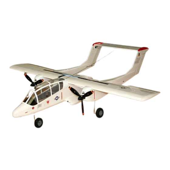
OV-10 BRONCO
KIT INCLUDES
Full size plan.
Lasercut parts.
1.5mm(1/16")xL600mm(24") balsa : 7sheets
1.5mm(1/16")xL460mm(18.2") balsa : 18sheets
1.5mm(1/16")xL320mm(12.6") balsa : 7sheets
3.0mm(1/8")xL600mm(24") balsa : 2sheets
3.0mm(1/8")xL460mm(18.2") balsa : 9sheets
3.0mm(1/8")xL320mm(12.6") balsa : 2sheets
5.0mm(3/16") xL550mm(21.7") balsa : 1sheet
5.0mm(3/16") xL370mm(14.6") balsa : 1sheet
1.8mm(5/64")xL200mm(8") plywood : 2sheets
3.0mm(1/8")xL600mm(24") plywood : 4sheets
Vacuum formed Cowls and Canopy.
Motor mounts 10x10x90mm.
Landing gears(3ea),
2mm bolts/nuts(4sets), 3mm screws(4ea), 2mm screws(16ea).
5mm Wing dowels(6ea), 4mm Wing bolts (3ea).
CA hinge.
Pushrods(7ea) for Rudders, Elevator, Ailerons and flaps.
Instructions and Stickers.
Download full color instructions from
http://www.estarmodels.com [Download] menu.
INSTRUCTIONS
Page 1
ITEMS NEEDED TO COMPLETE
Two GWS EPS-400C-DS(3:1) or
Two BL motors(5:1 geared, 9~12A).
Brushed : 1 ESC (30~35A)
Brushless : 2 ESC (15~20A).
Propeller 9070 (2-blades or 3-
blades) or APC 9x6E.
Li-Poly 11.1V 3000~3400mAh
(brushed) / 2400~3000mAh
(brushless) battery w/Li-Poly
charger.
www.estarmodels.com
Mini Receiver(5-7 channel).
7 submicro Servos
(Hitec HS-55 / Futaba S3108 /
GWS pico servos, or
equivalant).
Servo extension cords and Y-
harness.
1 mini metal geared servo for
nose steering(Optional).
2~3 rolls of covering film.
(Solite/Monokote/Oracover)
1-60mm and 2-70mm Wheels,
Wheel Collars(5~7ea) and Rod
adjusters(7ea).
Advertisement

Related Manuals for Estar OV-10 BRONCO

Summary of Contents for Estar OV-10 BRONCO
- Page 1 OV-10 BRONCO INSTRUCTIONS www.estarmodels.com KIT INCLUDES ITEMS NEEDED TO COMPLETE Mini Receiver(5-7 channel). Full size plan. Two GWS EPS-400C-DS(3:1) or Lasercut parts. Two BL motors(5:1 geared, 9~12A). 1.5mm(1/16”)xL600mm(24”) balsa : 7sheets 1.5mm(1/16”)xL460mm(18.2”) balsa : 18sheets 7 submicro Servos 1.5mm(1/16”)xL320mm(12.6”) balsa : 7sheets...
-
Page 2: Vertical Fin And Rudder
PREPARATION Remove parts from laser-cut panel and group as shown above. 5. Glue vertical fin sheets(V1a-V2, V1b-V2) together. VERTICAL FIN and RUDDER 6. Lay elevator servo extension cord and glue the parts(V3- V10) on the outboard vertical fin sheet(V1a,V2) with thin CA and apply thick CA glue at each joints for reinforcing. -
Page 3: Stabilizer And Elevator
10. Carefully sand surfaces. 16. Glue the leading edges(H7, E5) and trailing edge(H6) with thick CA. STABILIZER and ELEVATOR 11. Glue the sub leading edge and sub trailing edge(H2), ribs(H3-H4) on the stabilizer bottom sheet(H1) with thin CA and apply thick CA glue at each joints for reinforcing. 17. - Page 4 2. Glue right and left spars (W1-W1, W2-W2). Glue plywood spars(W3) with thick CA. 4. After sand leading edges, and then glue aileron leading edge(A5) with thick CA. Carefully sand surfaces. 3. Assemble bottom spars(W1-W3), ribs(W4-W12), wing bolt mounts(W13-W14,W16-W17) and dowel mounts(W15,W18). Note Balsa mounts(W14,W17) must be located under the 5.
- Page 5 3. Assemble plywood doubler(F2), longerons(F3a,F4a, F5a, F5b) and bulkheads(F7-F9,F13-F14) on the right side sheet (F1a, F1b) and then, glue with thin CA. 8. Apply wood glue as shown. Note Make sure to pay attention to all the bulkheads, the part numbers should be facing forward. 9.
- Page 6 9. Assemble and bottom sheet(F24a,F24b) with thick CA. 15. Assemble and glue rear fuselage frames(F3b,F4b,F4c, F5c,F10-F12,F23c,F25b) with thick CA. 10. Assemble and glue longerones(F27-F28) with thick CA. 16. Assemble and glue rear fuselage sheets(F1c,F24c, F26b) with thick CA. And then, sand edges. 11.
- Page 7 6. Sand the end of longerons(B21,B4b) as shown. 2. Glue side sheets(B22i,B22o) and bottom sheets(B23a- B23c) each together. 7. Assemble plywood bulkheads(B16-B19), longerons(B20- B21) with thin CA. Apply thick CA glue at each joints for reinforcing. 3. Assemble plywood doubler(B2), longerons(B3,B4a,B4b, B5), servo bed(B7a) and bulkheads(B6,B7,B8R,B9R, B15R) on the right side sheet(B1) and then, glue with thin CA.
- Page 8 16. Insert and glue wing dowels. Shape and sand the surfaces. 11. Assemble flap joiner cap (B26-B30). 17. Glue trailing edge(W39) with thick CA. Note Refer to the wing section on the drawing and use cardboard to make a gap. ...
- Page 9 COVERING AND EQUIPMENT INSTALLATION 3. Glue leading(N12), trailing edges(N13) and tips(N14) with thick CA. 1. Cover films with your own color scheme. 4. Carefully sand surfaces. 2. Assemble tail and insert elevator servo extension. 5. Glue sponson to the fuselage with thick CA. 3.
- Page 10 6. Install elevator servo. 11. Insert flap hinges(FH) and temporarily glue with small amount of CA. After throwing check, and then glue them firmly. Install aileron and flap servos. When you connect flap servos with Y-harness, install additional flap horn(F). 7.
- Page 11 15. Install main gear and then fix plywood retainers (B14) with screws. Fix wheels with wheel collars. With Landing gear. 16. Glue hinges to the stabilizer with small amount of thin CA and then, connect elevator pushrod. Without Landing gear / Retracts. Control Throws The following control throws are recommended starting points.
Need help?
Do you have a question about the OV-10 BRONCO and is the answer not in the manual?
Questions and answers