
Related Manuals for HP 41802A


Summary of Contents for HP 41802A
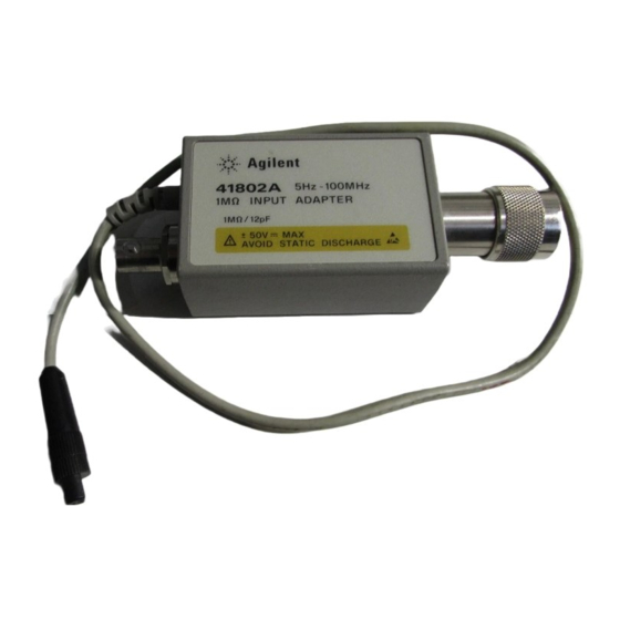
- Page 1 HP 41802A 1 M Input Adapter Operation Note SERIAL NUMBERS ABCDE HP Part No. 41802-90000 Printed in Japan February, 1999 2nd Edition...
- Page 3 Certi cation Warranty and Assistance Limitation of Warranty No other warranty is expressed or implied. HP speci cally disclaims the implied warranties of merchantability and tness for a particular purpose.
- Page 4 Caution...
- Page 5 Contents 1. General Information 2. Installation 3. Operation Contents-1...
- Page 6 4. Performance Test 5. Adjustment 6. Replaceable Parts A. Manual Changes Contents-2...
- Page 7 Figures Tables Contents-3...
- Page 9 General Information Introduction General Information...
- Page 10 Compatible Equipment Compatible Instruments Compatible Probes General Information...
- Page 11 Serial Number Figure 1-1. Serial Number Plate General Information...
- Page 12 Speci cations > > Figure 1-2. Speci cations General Information...
- Page 13 Supplemental Performance Characteristics Figure 1-3. Supplemental Characteristics General Information...
- Page 15 Installation Introduction Installation...
- Page 16 Initial Inspection Caution Figure 2-1. Product Overview Installation...
- Page 17 Power Requirements Figure 2-2. Probe Power Requirements Table 2-1. Probe Power Requirements Voltage Current Mating Connectors Note Caution Installation...
- Page 18 Environmental Requirements Installation...
- Page 19 Operation Introduction Operation...
- Page 20 Operating Precautions Anti-static Precautions Caution Table 3-1. Anti-static Products Available Description HP Part Number Operation...
- Page 21 Maximum Allowable Level Caution Discharging the Probe Caution Probe Power Plug Note Preparation for Use Operation...
- Page 22 Operating Check Using a Network Analyzer Using an HP 8751A or HP 3577A/B Network Analyzer Equipment Required. Procedure. Figure 3-1. Operating Check Setup Using HP 8751A or HP 3577A/B Network Analyzer Note Operation...
- Page 23 Using HP 8753A/B/C Network Analyzer Equipment Required. Procedure. Figure 3-2. Operating Check Setup Using HP 8753A/B/C Network Analyzer Note Operation...
- Page 24 Operating Check Using a Spectrum Analyzer Equipment Required Procedure Note Figure 3-3. Operating Check Setup Using Spectrum Analyzer Operation...
- Page 25 Operating Check Using a Network/Spectrum Analyzer Equipment Required Procedure Figure 3-4. Operating Check Setup Using Network/Spectrum Analyzer Operation...
- Page 26 Adjusting the Probe Using a Network Analyzer Equipment Required. Procedure. Figure 3-5. Probe Adjustment Setup Using a Network Analyzer|1 Operation...
- Page 27 Figure 3-6. Probe Adjustment Setup Using a Network Analyzer|2 Note Operation...
- Page 28 Using a Spectrum Analyzer Equipment Required. Procedure. Note Figure 3-7. Probe Adjustment Setup Using Spectrum Analyzer 3-10 Operation...
- Page 29 Typical Measurement Setups Caution Note Operation 3-11...
- Page 30 Network Measurements Using One HP 41802A Figure 3-8. Network Measurement Setup Example (Using One HP 41802A) 3-12 Operation...
- Page 31 Using One HP 41802A with a Transmission/Re ection Test Set Figure 3-9. Network Measurement Setup Example (Using with a Transmission/Re ection Set) Operation 3-13...
- Page 32 Using Two HP 41802As Figure 3-10. Network Measurement Setup Example (Using Two HP 41802As) Note 3-14 Operation...
- Page 33 Spectrum Measurements Figure 3-11. Spectrum Measurement Setup Example Operation 3-15...
- Page 34 Using HP 41802A with instruments which have BNC connectors Figure 3-12. Measurement Setup Example (BNC input connector) 3-16 Operation...
- Page 35 Performance Test Introduction Equipment Required Table 4-1. Recommended Test Equipment Equipment Critical Speci cations Recommended Model Qty. Performance T est...
- Page 36 Calibration Cycle Preparation Performance T est...
- Page 37 Gain Accuracy/Flatness Tests Description Speci cations Test Equipment Procedure Figure 4-1. Test Setup 1 Performance T est...
- Page 38 Control Settings Key Strokes PRESET START STOP NNNNNNNNNNN MEAS NNNNNNNNNNNNNNNNNNNNNNNNNNNNNNNNNNNNNNNNNNNNNNNNNN NUMBER of POINTS MENU NNNNNNNNNNNNNNNNNNNNNNNNNN NNNNNNNNNNNNNNNNNNNNNNNNNNNNNNNNNNNNNNNNNNNNNNN SWEEP TYPE MENU LOG FREQ MENU NNNNNNNNNNNNNNNNN IF BW NNNNNNNNNNNNNNNNN POWER MENU NNNNNNNNNNNNNNNNNNNNNNNNNNNNNNNNNNNNNNNNNNNNNNNNNN NNNNNNNNNNNNNNNNNNNNNNNNNNNNNNNNNNNNNNNNNNNNNNNNNNNNN MARKER MODE MENU MARKERS: DISCRETE NNNNNNNNNNNNNNNNNNNNNNNNNNNNNNNNNNNNNNNNNNNN NNNNNNNNNNNNNNNNNNNNNNNNNN NNNNNNNNNNNNNN NNNNNNNNNNNNNNNNNNNNNNNNNNNNNNNNNNNNNNNNN CALIBRATE MENU RESPONSE THRU DONE:RESPONSE...
- Page 39 Test Frequency Performance T est...
- Page 40 Performance Test Record Gain Accuracy/Flatness Tests Minimum Limit Test Result Maximum Limit Measurement Uncertainty Frequency Reading Minimum Test Result Maximum Measurement Limit [ a+b] Limit Uncertainty Performance T est...
- Page 41 Adjustment Introduction Equipment Required Preparation Adjustment...
- Page 42 Gain Adjustment Description Equipment Procedure Figure 5-1. Adjustment Setup 1 Adjustment...
- Page 43 Control Settings Key Strokes PRESET CENTER SPAN NNNNNNNNNNN MEAS NNNNNNNNNNNNNNNNNNNNNNNNNNNNNNNNNNNNNNNNNNNNNNNNNN NUMBER of POINTS MENU NNNNNNNNNNNNNNNNN IF BW NNNNNNNNNNNNNNNNN POWER MENU NNNNNNNNNNNNNNNNNNNNNNNNNNNNNNNNNNNNNNNNNNNNNNNNNN NNNNNNNNNNNNNNNNNNNNNNNNNNNNNNNNNNNNNNNNNNNNNNN MARKER MODE MENU MARKER DESCRETE SCALE REF NNNNNNNNNNNNNNNNNNNNNNNNNNNNNNNNNNNNNNNNNNNN NNNNNNNNNNNNNNNNNNNNNNNNNN NNNNNNNNNNNNNN NNNNNNNNNNNNNNNNNNNNNNNNNNNNNNNNNNNNNNNNN CALIBRATE MENU RESPONSE THRU DONE:RESPONSE Figure 5-2. Adjustment Setup 2 Adjustment...
- Page 44 Figure 5-3. Adjustment Setup 3 Adjustment...
- Page 45 Replaceable Parts Replaceable Parts Lists Table 6-1. Component Manufactures Mfr # Name Location Zipcode 28480 HEWLETT-PACKARD CO CORPORATE HQ PALO ALTO CA US 94304 78189 ILLINOIS TOOL WORKS INC SHAKEPROOF ELGIN IL US 60126 Replaceable Parts...
- Page 46 Figure 6-1. Replaceable Parts (1 of 2) Replaceable Parts...
- Page 47 Table 6-2. Replaceable Parts (2 of 2) Part No. Qty. Description Mfr. Mfr. Part No. Replaceable Parts...
- Page 48 Figure 6-2. Replaceable Parts (2 of 2) Table 6-3. Replaceable Parts (2 of 2) Part No. Qty. Description Mfr. Mfr. Part No. Replaceable Parts...
- Page 49 Manual Changes Introduction Manual Changes MANUAL CHANGES Table A-1. Manual Changes by Serial Number Serial Pre x Make Manual Changes or Number Manual Changes...
Need help?
Do you have a question about the 41802A and is the answer not in the manual?
Questions and answers