Table of Contents
Advertisement
Quick Links
Advertisement
Table of Contents

Related Manuals for CAMERA LINK vieworks VC Series


Summary of Contents for CAMERA LINK vieworks VC Series
- Page 2 VC Camera Link series Revision History Revision Date Description 2010-10-01 Initial release Added “scl” and “gcl” command 2010-12-13 2010-12-21 Added VC-2MC-M/C340 model 2011-04-07 Revised Max. Frame Rate 2011-07-12 Added 2 Tap and 4 Tap 10 bit Added VC-2MC-150 and VC-4MC-80 ...
- Page 3 VC Camera Link series Revision Date Description 2017-03-24 Added the VC-25MC2-30 (PYTHON-25K) 2018-01-19 Added the Flat Field Selector feature to VC-12MC-65 Added a note indicating the Strobe Offset (Strobe Delay) feature is only 2018-07-20 available on VC-25MC/VC-25MC2. Page 3 of 86...
-
Page 4: Table Of Contents
Precaution about blurring compared to the center ............. 24 Controlling the Camera ...................... 24 Camera Interface ......................25 General Description ......................25 Camera Link Connector ..................... 25 Power Input Connector ....................... 29 Control Connecter ......................30 Trigger Input Circuit ......................31 Strobe Output Circuit ...................... - Page 5 Free-Run Mode ..........................43 8.5.2 External Sync Mode ........................44 8.5.3 Overlap Trigger Input ........................45 Camera Link Output ......................46 Gain and Offset ........................47 Defective Pixel Correction ....................48 8.8.1 Correction Method ........................... 48 Flat Field Correction (VC-2MC-340/VC-4MC-180/VC-12MC/VC-25MC/VC-25MC2 Only) 49 8.9.1...
- Page 6 VC Camera Link series 10.3 Tab ............................73 10.3.1 VIEW tab ............................73 10.3.2 MODE/EXP Tap ..........................75 10.3.3 ANALOG Tab ........................... 76 10.3.4 FFC Tab ............................77 Troubleshooting ......................78 Appendix A Defective Pixel Map Download ..............79 Appendix B Field Upgrade....................
-
Page 7: Precautions
VC Camera Link series 1 Precautions General Do not drop, disassemble, repair or alter the device. Doing so may damage the camera electronics and cause an electric shock. Do not let children touch the device without supervision. ... -
Page 8: Warranty
VC Camera Link series 2 Warranty For information about the warranty, please contact your local dealer or factory representative. 3 Compliance & Certifications FCC Compliance This equipment has been tested and found to comply with the limits for a Class A digital device, pursuant to part 15 of the FCC Rules. -
Page 9: Package Components
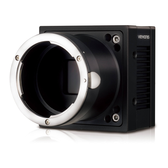
VC Camera Link series 4 Package Components Package Components VC Camera <C-mount> VC Camera <F-mount> Mount Plate (Optional) M5 Set Screws for Tilt Adjustment (Provided only with F-mount camera) You can adjust the tilt using the M5 set screws, however it is not recommended since it is adjusted as factory default settings. -
Page 10: Product Specifications
VC-3MC / 25MC / 25MC2: 8 Tap, 10 Tap Gain/Offset Control Test Image LVDS (RS-644) serial communication by Camera Link interface Temperature monitor Field upgrade Dark image correction (Supported only on VC-2MC / 3MC / 4MC / 12MC) ... -
Page 11: Specifications
85 ㎒ Camera Link Pixel Clock 1/100000 ~ 7 sec (10 ㎲ step) Exposure Time < 5 m (Camera Link Cable at 85 ㎒) Cable Length Black Offset 0 ~ 63 LSB, 64 step 0 ~ 12 ㏈, 64 step... - Page 12 Camera Link Pixel Clock 1/100000 ~ 7 sec (10 ㎲ step) 5/100000~7sec (10 ㎲ step) Exposure Time < 5 m (Camera Link Cable at 85 ㎒) Cable Length Black Offset 0 ~ 63 LSB, 64 step 0 ~ 12 ㏈, 64 step...
- Page 13 85 ㎒ Camera Link Pixel Clock 1/100000 ~ 7 sec (10 ㎲ step) Exposure Time < 5 m (Camera Link Cable at 85 ㎒) Cable Length Black Offset 0 ~ 63 LSB, 64 step 0 ~ 12 ㏈, 64 step...
-
Page 14: Camera Block Diagram
Camera Link interface and then processes them. The Processing & Control Logic processes the image data received from the CMOS sensor and then transmits data through the Camera Link interface. And also, the Processing & Control Logic controls the trigger inputs and strobe outputs which are sensitive to time. -
Page 15: Sensor Information
VC Camera Link series Sensor Information The following graphs show the spectral response for VC-2MC monochrome and color camera. Figure 5.2 Mono Spectral Response for VC-2MC Figure 5.3 Color Spectral Response for VC-2MC Page 15 of 86 RA14-11A-010... - Page 16 VC Camera Link series The following graph shows the spectral response for VC-3MC monochrome and color camera. Figure 5.4 Mono and Color Spectral Response for VC-3MC Page 16 of 86 RA14-11A-010...
- Page 17 VC Camera Link series The following graphs show the spectral response for VC-4MC monochrome and color camera. Figure 5.5 Mono Spectral Response for VC-4MC Figure 5.6 Color Spectral Response for VC-4MC Page 17 of 86 RA14-11A-010...
- Page 18 VC Camera Link series The following graph shows the spectral response for VC-12MC monochrome and color camera. Figure 5.7 Mono and Color Spectral Response for VC-12MC Page 18 of 86 RA14-11A-010...
- Page 19 VC Camera Link series The following graph shows the spectral response for VC-25MC monochrome and color camera. Figure 5.8 Mono and Color Spectral Response for VC-25MC The following graph shows the spectral response for VC-25MC2 monochrome and color camera. Figure 5.9 Mono and Color Spectral Response for VC-25MC2...
-
Page 20: Mechanical Specification
VC Camera Link series Mechanical Specification The camera dimensions in millimeters are as shown in the following figures. Figure 5.10 VC-2MC / 3MC / 4MC Camera Link C-mount Mechanical Dimension Page 20 of 86 RA14-11A-010... - Page 21 VC Camera Link series Figure 5.11 VC-2MC / 3MC / 4MC Camera Link F-mount Mechanical Dimension Page 21 of 86 RA14-11A-010...
- Page 22 VC Camera Link series Figure 5.12 VC-12MC / 25MC / 25MC2 Camera Link F-mount Mechanical Dimension Page 22 of 86 RA14-11A-010...
-
Page 23: Connecting The Camera
Make sure that the power supply is not connected to the camera and your PC is turned off. Plug one end of a Camera Link cable into the Camera Link connector on the camera and the other end of the Camera Link cable into the connector on your Camera Link frame grabber. -
Page 24: Precaution To Center The Image Sensor
Controlling the Camera You can control the camera by executing the Configurator.exe file. You can download the latest Configurator at http://www.vieworks.com. Please refer to your Camera Link frame grabber user manual. Page 24 of 86 RA14-11A-010... -
Page 25: Camera Interface
① 26 pin Camera Link Connector 1 (Base): controls video data transmission and the camera. ② 26 pin Camera Link Connector 2 (Medium/Full): transmits video data ③ Status LED: displays power status and operation mode. - Page 26 VC Camera Link series Camera output complies with Camera Link Standard and the following list shows the pin configuration of the connector. PAIR List Signal Name Type Description Ground Ground Cable Shield PAIR 0 Ground Ground Cable Shield LVDS - Out...
- Page 27 LVDS - Out Camera Link Channel Tx PAIR 11 LVDS - Out Camera Link Channel Tx Ground Ground Cable Shield PAIR 12 Ground Ground Cable Shield Table 7.2 Pin Assignments for Camera Link Connector 2 Page 27 of 86 RA14-11A-010...
- Page 28 VC-25MC2-30 Table 7.3 Connector Arrangement for Camera Link Output Modes When you connect a Frame Grabber to Camera Link Connectors using Camera Link cables, make sure you connect to the correct Camera Link Connector. Incorrect connection of Connector 1 and Connector 2 may cause malfunction of the camera or communication problems between PC and the camera.
-
Page 29: Power Input Connector
VC Camera Link series Power Input Connector The power input connector is a Hirose 6 pin connector (part # HR10A-7R-6PB). Pin arrangement and configuration are as follows: Figure 7.3 Pin Arrangement of Power Input Connector Pin Number Signal Type Description... -
Page 30: Control Connecter
VC Camera Link series Control Connecter The control connector is a Hirose 4 pin connector (part # HR10A-7R-4S) and consists of an external trigger signal input and strobe output port. Pin arrangement and configuration are as follows: Figure 7.4 Pin Arrangement of Control Connector... -
Page 31: Trigger Input Circuit
VC Camera Link series Trigger Input Circuit Following figure shows trigger signal input circuit of the 4-pin connector. Transmitted trigger signal is applied to the internal circuit through a photo coupler. Minimum trigger width that can be recognized by the camera is 1 ㎲. -
Page 32: Strobe Output Circuit
VC Camera Link series Strobe Output Circuit The strobe output signal is 3.3 V output level of a TTL Driver IC. The pulse width of signal is synchronized with the exposure signal (shutter) of the camera. +3.3V 3.3 V 3.3 V 47 Ω... -
Page 33: Camera Features
VC Camera Link series 8 Camera Features Region Of Interest (ROI) The Region of Interest (ROI) feature allows you to specify a portion of the sensor array. You can acquire only the frame data from the specified portion of the sensor array while preserving the same quality as you acquire a frame from the entire sensor array. - Page 34 VC Camera Link series In VC-3MC, the maximum frame rates depending on the changes of both horizontal and vertical ROI are shown in the following table. ROI Size (H × V) 8 Tap 10 Tap 640 × 480 1830 fps 2288 fps 1024 ×...
- Page 35 30.1 fps Table 8.5 VC-25MC and VC-25MC2 Maximum Frame Rate depending on ROI Size The ROI values (H × V) may vary depending on the type of Camera Link frame grabber. For technical assistance, contact your local dealer or the manufacturer.
-
Page 36: Multi-Roi (Vc-12Mc/Vc-25Mc/Vc-25Mc2 Only)
VC Camera Link series Multi-ROI (VC-12MC/VC-25MC/VC-25MC2 Only) The VC-12MC-65, VC-25MV-30 and VC-25MC2 cameras provide the Multi-ROI feature which allows you to define up to thirty two regions on the sensor array. When an image is acquired, only the pixel information from the defined regions will be readout of the sensor. - Page 37 VC Camera Link series There are several things to keep in mind when setting the Multi-ROI feature on the VC-12MC camera: The sum of the Offset X value plus the Width value must not exceed the width (4096 on the VC-12MC) of the camera’s sensor.
-
Page 38: Multi-Roi On Vc-25Mc / Vc-25Mc2
VC Camera Link series 8.2.2 Multi-ROI on VC-25MC / VC-25MC2 It is recommended that you first set the Width parameter, since all of the regions must be the same width. The next step in the setup process is to define each individual region as desired. Up to 32 regions can be set up ranging from 0 through 31. - Page 39 VC Camera Link series There are several things to keep in mind when setting the Multi-ROI feature on the VC-25MC and VC-25MC2 cameras: The sum of the Offset X value plus the Width value must not exceed the width (5120 on the VC-25MC / VC- 25MC2) of the camera’s sensor.
-
Page 40: Binning (Vc-25Mc / Vc-25Mc2 Monochrome Only)
VC Camera Link series Binning (VC-25MC / VC-25MC2 Monochrome Only) Binning has the effects of increasing the level value and decreasing resolution by adding the values of the adjacent pixels and sending them as one pixel. VC-25MC provides two binning factor (×1 and ×2) that the user can apply both horizontally and vertically. -
Page 41: Exposure
VC Camera Link series Exposure The CMOS sensor of VC series uses global shutter that exposes the entire imager simultaneously. The below figure illustrates the timing of exposure and readout of CMOS sensor. Readout is performed consecutively from first to last line where readout defines the process of reading the accumulated charges on pixels. Readout Time (also called Transfer Time) defines the rate at which one frame of an image is transferred. -
Page 42: Real Exposure (Vc-12Mc Only)
Figure 8.5. This offset value varies depending on the camera’s Camera Link Output Mode settings. The setting value on the exposure time is equal to actual exposure time, because the offset value is compensated on the actual exposure time. In 8 tap output channel mode, for example, the exposure time is set to 200 ㎲. -
Page 43: Trigger Mode
VC Camera Link series Trigger Mode Trigger mode of the camera is divided into Free-Run mode where image is synchronized to Internal Trigger signal created inside the camera and External Sync mode where image is synchronized to the trigger signal entered into the external port. -
Page 44: External Sync Mode
VC Camera Link series 8.5.2 External Sync Mode In External Sync Mode, camera keeps standby status until trigger signal is entered, and when trigger is entered, the image is transmitted (frame transfer) after exposure process. To operate the camera in External Sync mode, it is required to set Trigger Source regarding which input, CC1 input port or External Trigger port, will be used for trigger signal, as well as Polarity and Exposure source of the signal entered. -
Page 45: Overlap Trigger Input
VC Camera Link series 8.5.3 Overlap Trigger Input When trigger is entered during frame transfer as shown in the figure below, it performs exposure process for newly entered trigger while transferring the previous data. In this case, shooting images is possible up to the maximum frame rate (speed of 1/Transfer Time (sec)) regardless of the exposure time. -
Page 46: Camera Link Output
1 Pixel Clock Cycle 10 Tap Output (FULL *1) 1 Pixel Clock Cycle *1 : Camera-Link Configuration Figure 8.11 Camera Link Output Mode † Supported Camera Link Output Mode VC-2MC-150 and VC-4MC-80 support 2 Tap and 4 Tap. ... -
Page 47: Gain And Offset
VC Camera Link series Gain and Offset Gain and Offset can be changed through Voltage Reference adjustment which is applied commonly to all ADCs. Gain adjustment can be set among 0 ~ 12 ㏈ and setting value can be set as a value from 0 to 64 step. -
Page 48: Defective Pixel Correction
VC Camera Link series Defective Pixel Correction The CMOS sensor may have Defect Pixels which cannot properly react to the light. Correction is required since it may deteriorate the quality of output image. Defect Pixel information of CMOS used for each camera is entered into the camera during the manufacturing process. -
Page 49: Flat Field Correction (Vc-2Mc-340/Vc-4Mc-180/Vc-12Mc/Vc-25Mc/Vc-25Mc2 Only)
VC Camera Link series Flat Field Correction (VC-2MC-340/VC-4MC-180/VC-12MC/VC-25MC/VC-25MC2 Only) The Flat Field Correction feature improves the image uniformity when you acquire a non-uniformity image due to external conditions. The Flat Field Correction feature can be summarized by the following equation:... - Page 50 VC Camera Link series Figure 8.14 Generation and Application of Flat Field Data Figure 8.15 Bilinear Interpolated Magnification Page 50 of 86 RA14-11A-010...
-
Page 51: Flat Field Selector (Vc-12Mc/Vc-25Mc/Vc-25Mc2 Only)
VC Camera Link series 8.9.1 Flat Field Selector (VC-12MC/VC-25MC/VC-25MC2 Only) As mentioned above, the active Flat Field data is stored in the camera’s volatile memory and the data is lost if the camera is reset of powered off. To use the active or generated Flat Field data after the camera is powered on or reset, you need to save them in the camera’s non-volatile memory. -
Page 52: High Dynamic Range (Vc-2Mc-M340/Vc-4Mc-180 Only)
VC Camera Link series 8.10 High Dynamic Range (VC-2MC-M340/VC-4MC-180 Only) When you acquire images in some situations where a bright light source or shiny materials are located within the field of view, the light areas appear overexposed in the acquired images. And if you use a short exposure time to avoid overexposure in the light areas of the acquired images, all details will be lost in the darker areas. -
Page 53: Auto White Balance (Vc-12Mc/Vc-25Mc/Vc-25Mc2 Only)
VC Camera Link series 8.11 Auto White Balance (VC-12MC/VC-25MC/VC-25MC2 Only) The Auto White Balance feature is implemented on the VC-12MC-C65, VC-25MC-C30 and VC-25MC2-C30 color cameras. It will control the white balance of the image acquired from the color camera according to the GreyWorld algorithm. -
Page 54: Data Format
VC Camera Link series 8.14 Data Format † Data can be processed in the unit of 10 bit internally, but can be selectively output in the unit of 8 or 10 bit output. When it is output in 8 bit unit, the 2 least significant bits will be dropped from overall 10 bits. -
Page 55: Test Image
VC Camera Link series 8.15 Test Image To check normal operation of the camera, it can be set to output test image created inside, instead of image data from the imaging sensor. There are 3 types of test image; image with different value in horizontal direction (Test Image 1), image with different value in diagonal direction (Test Image 2), and moving image with different value in diagonal direction (Test Image 3). -
Page 56: Strobe
VC Camera Link series 8.16 Strobe The camera can provide a Strobe output signal. The signal goes high when the exposure time for each frame acquisition begins and goes low when the exposure time ends as shown in the figure below. This signal can be used as a flash trigger and is also useful when you are operating a system where either the camera or the object being imaged is movable. -
Page 57: Field Upgrade
VC Camera Link series 8.17 Field Upgrade The camera has the function to upgrade firmware and FGPA logic through RS-644 interface of Camera Link, rather than disassemble the camera in the field. See Appendix B for details on how to upgrade. -
Page 58: Dark Image Correction
VC Camera Link series 8.18 Dark Image Correction CMOS sensor may result in lower sensitivity at dark level. This is caused by fixed pattern noise variation depending on the exposure settings or characteristic change according to the temperature variation of AFE and sensor cell. -
Page 59: White Pixel
VC Camera Link series 8.19 White Pixel If you use a VC-25MC or VC-25MC2 camera under the condition of high ambient temperature, white pixels (also known as hot pixels) may be occurred due to the characteristic of equipped high resolution CMOS sensor. -
Page 60: Camera Configuration
VC Camera Link series 9 Camera Configuration Setup Command All the settings for the camera are carried out through RS-644 serial interface of camera link. With the following communication setting, it can be controlled using terminal or direct control at user application. ... - Page 61 VC Camera Link series If execution of read command is successfully completed <parameter1> <cr> <lf> ex) Read command In response to a “get” command the camera will return (in hex value) Command : 67 65 74 0D get <cr> Response...
-
Page 62: Actual Time Applied For Commands
VC Camera Link series Actual Time Applied for Commands When you execute a command, the actual or real time applied for the command varies depending on the type of the command and operating status of the camera. All commands except Set Exposure Time (“set”) command are applied to change the settings as illustrated below, on the rising edge of a VCCD signal before starting readout process. -
Page 63: Parameter Storage Space
VC Camera Link series Parameter Storage Space The camera has 3 non-volatile storage space used for parameter storage and 1 volatile work space that is applied to actual camera operation. 3 storage space is divided into Factory Space that contain basic value at the factory, and 2 user space (User Space 1, User Space 2) that can save parameter value temporarily set by the user. -
Page 64: Command List
VC Camera Link series Command List Command Syntax Value Returned Description Help String Display a list of all commands 0: Normal mode Set Read-Out Mode srm 0|1 1: ROI (Region of Interest) mode Get Read-Out Mode (ROI is set using “sha” and “sva” commands.) - Page 65 VC Camera Link series Value Command Syntax Description Returned Generate Offset Calibration Data Generate offset calibration data to the volatile memory Save Offset Calibration Data Save offset calibration data to the flash memory Load offset calibration data from the flash...
- Page 66 VC Camera Link series Value Command Syntax Description Returned Set Region Select srs n n: Region number (0 - 31) Get Region Select Set Region Mode (current region) src 0|1 0: Region Off Get Region Mode (current region) 1: Region On...
- Page 67 VC Camera Link series Value Command Syntax Description Returned Set HDR Mode shm 0|1 0: Normal mode Get HDR Mode 1: High Dynamic Range mode n: Dynamic range in ㏈ Set High Dynamic range shd n (Setting range: 0 ~ 40 ㏈) Table 9.6 Command List #6 (High Dynamic Range)
-
Page 68: Configurator Gui
When you execute the program while the camera is turned on, Camera Scan window appears as shown in the figure below. At this time, the program checks serial port of computer and DLL provided by Camera Link to scan whether the camera is connected. If there is a camera connected, it displays model name on the screen. If the camera is not properly displayed on the screen, check the connection of cable with power of camera and press the refresh button. -
Page 69: Menu
VC Camera Link series 10.2 Menu 10.2.1 File Figure 10.2 File Menu Load Setting: Loads the camera setting value from the camera memory (Factory, User1, User2) or user computer (From File). Save Setting: Saves the camera setting values to the camera memory (User1 or User2) or user computer (To File). -
Page 70: Start-Up
VC Camera Link series 10.2.2 Start-Up You can select the camera setting values to load when the camera is turned on. Figure 10.3 Start-Up Menu Factory Setting: Loads the camera setting values from Factory Space. User1 Setting: Loads the camera setting values from User1 Space. -
Page 71: Tool
VC Camera Link series 10.2.3 Tool Figure 10.4 Tool Menu Refresh: Loads and displays the current camera setting values on Configurator. Terminal: Displays user commands in Terminal window under GUI. To hide Terminal window, uncheck Terminal by clicking again. -
Page 72: About
VC Camera Link series 10.2.4 About Figure 10.6 About Menu Camera Info: Displays camera information (product name, serial number, version, etc). Page 72 of 86 RA14-11A-010... -
Page 73: Tab
×2 option button is activated (Supported only on VC-25MC/VC-25MC2). Test Image: Selects whether to apply test image and the type of test image. Camera Link Output: Selects Camera Link output mode. Data Bit: Selects width of data output. Image Processing: Sets Defect Correction feature On or Off. - Page 74 VC Camera Link series Configurator provides the VIEW tab for the VC-12MC/VC-25MC/VC-25MC2 models as follows. Figure 10.8 VIEW tab for VC-12MC Full: Disables the Multi-ROI feature and set to its full resolution. ROI: Displays the Setting Multi-ROI window for setting Multi-ROI.
-
Page 75: Mode/Exp Tap
VC Camera Link series 10.3.2 MODE/EXP Tap MODE/EXP tab allows you to select trigger mode, exposure time and strobe. Figure 10.10 MODE/EXP Tab Trigger Mode: Selects trigger mode. Once a mode has been selected, related selections will be activated. -
Page 76: Analog Tab
VC Camera Link series 10.3.3 ANALOG Tab ANALOG tab allows you to set gain and offset settings of the image. Figure 10.11 ANALOG Tab Video Gain: Sets gain value. Video Offset: Sets offset value. Page 76 of 86... -
Page 77: Ffc Tab
VC Camera Link series 10.3.4 FFC Tab Configurator provides the FFC tab for the VC-2MC-340, VC-4MC-180, VC-12MC, VC-25MC and VC-25MC2 models as follows. Figure 10.12 FFC Tab FFC Data: Generates the Flat Field Correction data to be used for correction. -
Page 78: Troubleshooting
If there is a communication failure between the camera and PC, Ensure that the camera link cable is connected properly. Ensure that serial communication settings are configured properly on both PC and frame grabber. Page 78 of 86... -
Page 79: Appendix A Defective Pixel Map Download
VC Camera Link series Appendix A Defective Pixel Map Download Create the Defective Pixel Map data in Microsoft Excel format as shown in the left picture below and save as a CSV file (*.csv). The picture in the right shows the created Excel file opened in Notepad. The following rules need to be applied when creating the file. - Page 80 VC Camera Link series Search and select the created file and click Open. Configurator starts downloading defective pixel map data to the camera and downloading status is displayed at the bottom of the window. Page 80 of 86 RA14-11A-010...
- Page 81 VC Camera Link series Once the download has been completed, the saving process will begin. During the saving process, make sure not to disconnect the power cord. Once all the processes have been completed, Download completed message will appear at the bottom of the window.
-
Page 82: Appendix B Field Upgrade
VC Camera Link series Appendix B Field Upgrade Select File > System Upgrade > MCU Upgrade on Configurator. Search and select the provided MCU upgrade file (*.srec) then click Open. Page 82 of 86 RA14-11A-010... - Page 83 VC Camera Link series Configurator starts downloading MCU upgrade file to the camera and downloading status is displayed at the bottom of the window. If you want to cancel the upgrade process, click Cancel. This process requires several minutes to complete.
- Page 84 VC Camera Link series Once all the processes have been completed, turn the power off and turn it back on again. Select Tool > Terminal and enter the “gmv" command to confirm the version. Or, select About > Camera Info to confirm the MCU version.
-
Page 85: Fpga
VC Camera Link series FPGA Select File > System Upgrade > FPGA Upgrade on Configurator. Search and select the provided FPGA upgrade file (*.bin) and click Open. The subsequent processes are identical to those of MCU upgrade. Page 85 of 86... - Page 86 http://www.vieworks.com vieworks@vieworks.com...
Need help?
Do you have a question about the vieworks VC Series and is the answer not in the manual?
Questions and answers