Table of Contents
Advertisement
Quick Links
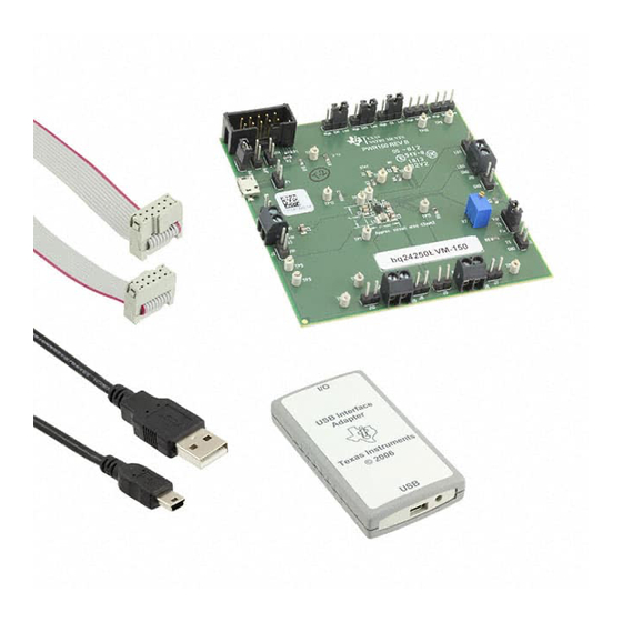
bq2425xEVM-150, Single-Cell Li-Ion Switch-Mode Charger
This user's guide describes the characteristics, operation, and use of the bq24250EVM-150,
bq24251EVM-150, and bq24257EVM-150 evaluation modules (EVM). These EVMs enable test and
evaluation TI's bq24250, bq24251, and bq24257 devices. The bq2425x series are highly integrated,
single-cell, Li-Ion battery chargers targeted for space-limited, portable applications with high-capacity
batteries. This user's guide includes EVM specifications, the schematic diagram, test procedures, test
results, a bill of materials, and board layout.
1
2
3
4
4.1
4.2
4.3
4.4
4.5
5
5.1
5.2
5.3
5.4
5.5
6
6.1
6.2
6.3
7
7.1
7.2
7.3
1
2
3
4
5
6
7
8
9
10
11
2
I
C is a trademark of NXP.
SLUUA08A - March 2013 - Revised April 2013
Submit Documentation Feedback
..................................................................................................................
........................................................................................................
.....................................................................................
................................................................................................
...........................................................................................................
......................................................................................................
..........................................................................................................
....................................................................................................
..............................................................................................................
............................................................................................................
.................................................................................
.............................................................................................................
................................................................................
................................................................................................................
........................................................................................
....................................................................................................
............................................................................................
..............................................................................................
..............................................................................................................
...........................................................................................
.............................................................................................
.........................................................................................................
...........................................................................................................
................................................................................................................
.............................................................................................................
.......................................................................................
......................................................................................
Copyright © 2013, Texas Instruments Incorporated
SLUUA08A - March 2013 - Revised April 2013
............................................................................
........................................................................
........................................................................
...............................................................
.......................................................................
.........................................................................
bq2425xEVM-150, Single-Cell Li-Ion Switch-Mode Charger
User's Guide
...................................
2
3
3
4
4
5
5
6
6
7
7
7
7
8
10
12
12
12
13
13
13
14
20
4
8
9
9
10
12
12
12
13
14
15
1
Advertisement
Table of Contents

Related Manuals for Texas Instruments bq2425xEVM-150


Summary of Contents for Texas Instruments bq2425xEVM-150
-
Page 1: Table Of Contents
User's Guide SLUUA08A – March 2013 – Revised April 2013 bq2425xEVM-150, Single-Cell Li-Ion Switch-Mode Charger This user's guide describes the characteristics, operation, and use of the bq24250EVM-150, bq24251EVM-150, and bq24257EVM-150 evaluation modules (EVM). These EVMs enable test and evaluation TI's bq24250, bq24251, and bq24257 devices. The bq2425x series are highly integrated, single-cell, Li-Ion battery chargers targeted for space-limited, portable applications with high-capacity batteries. -
Page 2: Contents 1 Introduction
Introduction www.ti.com .................... bq2425xEVM-150 Top Layer ..............bq2425xEVM-150 Second Layer (Internal) Routine ..............bq2425xEVM-150 Third Layer (Internal) Routine ..................bq2425xEVM-150 Bottom Layer List of Tables ....................Connector and Test Points ..................... Test Points Description ......................Pin Descriptions ....................Control and Key Parameters .................. -
Page 3: Evm Considerations
C default mode Output regulation voltage C host mode: operating in voltage regulation, 4.44 programmable range LDO output voltage SLUUA08A – March 2013 – Revised April 2013 bq2425xEVM-150, Single-Cell Li-Ion Switch-Mode Charger Submit Documentation Feedback Copyright © 2013, Texas Instruments Incorporated... -
Page 4: Equipment And Evm Setup
See U ser' s gui de f or part usage See U ser' s gui de f or vol t age rat i ngs Figure 1. bq2425xEVM-150 Schematic bq2425xEVM-150, Single-Cell Li-Ion Switch-Mode Charger SLUUA08A – March 2013 – Revised April 2013 Submit Documentation Feedback... -
Page 5: I/O Description
Test Point Description GND K CSIN/SYS STAT PG/INT TP10 TP11 ISET TP12 ILIM TP13 VDPM TP14 BOOT TP15 PMID SLUUA08A – March 2013 – Revised April 2013 bq2425xEVM-150, Single-Cell Li-Ion Switch-Mode Charger Submit Documentation Feedback Copyright © 2013, Texas Instruments Incorporated... -
Page 6: Pin Descriptions
Shorting jumper connects CE to J14 Shorting jumper connects D+/EN1 to J14 JP10 Shorting jumper connects D–/EN2 to J14 bq2425xEVM-150, Single-Cell Li-Ion Switch-Mode Charger SLUUA08A – March 2013 – Revised April 2013 Submit Documentation Feedback Copyright © 2013, Texas Instruments Incorporated... -
Page 7: Test Procedure
Note that all devices in the bq2425x family include a safety timer. If the time indicated in the Safety Timer Time Limit elapses, charging discontinues. If this occurs, a power reset or battery removal is required. SLUUA08A – March 2013 – Revised April 2013 bq2425xEVM-150, Single-Cell Li-Ion Switch-Mode Charger Submit Documentation Feedback Copyright © 2013, Texas Instruments Incorporated... -
Page 8: Recommended Test Equipment Set Up
2. Set power supply #1 (PS #1) for 6-V, 3-A current limit, then turn off supply. Windows USB-to GPIO (HPA172) Battery Emulator Figure 2. Original Test Setup bq2425xEVM-150, Single-Cell Li-Ion Switch-Mode Charger SLUUA08A – March 2013 – Revised April 2013 Submit Documentation Feedback Copyright © 2013, Texas Instruments Incorporated... -
Page 9: Battery Emulator
9. After the proceeding steps have been performed, the test setup for PWR150 is configured as is shown Figure SLUUA08A – March 2013 – Revised April 2013 bq2425xEVM-150, Single-Cell Li-Ion Switch-Mode Charger Submit Documentation Feedback Copyright © 2013, Texas Instruments Incorporated... -
Page 10: Recommended Test Procedure
Press the READ button to obtain the current settings. • Change the Input Current Limit to 100 mA bq2425xEVM-150, Single-Cell Li-Ion Switch-Mode Charger SLUUA08A – March 2013 – Revised April 2013 Submit Documentation Feedback Copyright © 2013, Texas Instruments Incorporated... - Page 11 Measure voltage on D+ (D+, JP2) to 0 V • Now you are exited the dead battery provision SLUUA08A – March 2013 – Revised April 2013 bq2425xEVM-150, Single-Cell Li-Ion Switch-Mode Charger Submit Documentation Feedback Copyright © 2013, Texas Instruments Incorporated...
-
Page 12: Test Results
1800 2000 Output Current (mA) C001 Figure 8. Efficiency Versus Output Current While in Battery Voltage Regulation (4.2V)” bq2425xEVM-150, Single-Cell Li-Ion Switch-Mode Charger SLUUA08A – March 2013 – Revised April 2013 Submit Documentation Feedback Copyright © 2013, Texas Instruments Incorporated... -
Page 13: Thermal Performance
This allows better thermal performance because the board conducts heat away from the IC. SLUUA08A – March 2013 – Revised April 2013 bq2425xEVM-150, Single-Cell Li-Ion Switch-Mode Charger Submit Documentation Feedback Copyright © 2013, Texas Instruments Incorporated... -
Page 14: Layout
Layout and Bill of Materials www.ti.com Layout Figure 10. bq2425xEVM-150 Top Assembly bq2425xEVM-150, Single-Cell Li-Ion Switch-Mode Charger SLUUA08A – March 2013 – Revised April 2013 Submit Documentation Feedback Copyright © 2013, Texas Instruments Incorporated... -
Page 15: Bq2425Xevm-150 Top Silkscreen
Layout and Bill of Materials www.ti.com Figure 11. bq2425xEVM-150 Top Silkscreen SLUUA08A – March 2013 – Revised April 2013 bq2425xEVM-150, Single-Cell Li-Ion Switch-Mode Charger Submit Documentation Feedback Copyright © 2013, Texas Instruments Incorporated... -
Page 16: Bq2425Xevm-150 Top Layer
Layout and Bill of Materials www.ti.com Figure 12. bq2425xEVM-150 Top Layer bq2425xEVM-150, Single-Cell Li-Ion Switch-Mode Charger SLUUA08A – March 2013 – Revised April 2013 Submit Documentation Feedback Copyright © 2013, Texas Instruments Incorporated... -
Page 17: Bq2425Xevm-150 Second Layer (Internal) Routine
Layout and Bill of Materials www.ti.com Figure 13. bq2425xEVM-150 Second Layer (Internal) Routine SLUUA08A – March 2013 – Revised April 2013 bq2425xEVM-150, Single-Cell Li-Ion Switch-Mode Charger Submit Documentation Feedback Copyright © 2013, Texas Instruments Incorporated... -
Page 18: Bq2425Xevm-150 Third Layer (Internal) Routine
Layout and Bill of Materials www.ti.com Figure 14. bq2425xEVM-150 Third Layer (Internal) Routine bq2425xEVM-150, Single-Cell Li-Ion Switch-Mode Charger SLUUA08A – March 2013 – Revised April 2013 Submit Documentation Feedback Copyright © 2013, Texas Instruments Incorporated... -
Page 19: Bq2425Xevm-150 Bottom Layer
Layout and Bill of Materials www.ti.com Figure 15. bq2425xEVM-150 Bottom Layer SLUUA08A – March 2013 – Revised April 2013 bq2425xEVM-150, Single-Cell Li-Ion Switch-Mode Charger Submit Documentation Feedback Copyright © 2013, Texas Instruments Incorporated... -
Page 20: Bill Of Materials (Bom)
Layout and Bill of Materials www.ti.com Bill of Materials (BOM) Table 5. bq2425xEVM-150 Bill of Materials COUNT RefDes Value Description Size Part Number C1, C7 1.0uF Capacitor, Ceramic, 25V, X5R, 20% 0805 1.0uF Capacitor, Ceramic, 16V, X5R, 10% 0402 0.033uF... - Page 21 Any exceptions to this are strictly prohibited and unauthorized by Texas Instruments unless user has obtained appropriate experimental/development licenses from local regulatory authorities, which is responsibility of user including its acceptable authorization.
- Page 22 FCC Interference Statement for Class B EVM devices This equipment has been tested and found to comply with the limits for a Class B digital device, pursuant to part 15 of the FCC Rules. These limits are designed to provide reasonable protection against harmful interference in a residential installation. This equipment generates, uses and can radiate radio frequency energy and, if not installed and used in accordance with the instructions, may cause harmful interference to radio communications.
- Page 23 Also, please do not transfer this product, unless you give the same notice above to the transferee. Please note that if you could not follow the instructions above, you will be subject to penalties of Radio Law of Japan. Texas Instruments Japan Limited (address) 24-1, Nishi-Shinjuku 6 chome, Shinjuku-ku, Tokyo, Japan http://www.tij.co.jp...
- Page 24 FDA Class III or similar classification, then you must specifically notify TI of such intent and enter into a separate Assurance and Indemnity Agreement. Mailing Address: Texas Instruments, Post Office Box 655303, Dallas, Texas 75265 Copyright © 2012, Texas Instruments Incorporated...
- Page 25 TI products. TI’s provision of these resources does not expand or otherwise alter TI’s applicable warranties or warranty disclaimers for TI products. TI objects to and rejects any additional or different terms you may have proposed. IMPORTANT NOTICE Mailing Address: Texas Instruments, Post Office Box 655303, Dallas, Texas 75265 Copyright © 2021, Texas Instruments Incorporated...
Need help?
Do you have a question about the bq2425xEVM-150 and is the answer not in the manual?
Questions and answers