
Related Manuals for ETS 5504


Summary of Contents for ETS 5504
- Page 1 Compact Environmental Chamber Model 5504 Operating Manual D01833 Revision A – 20211101 www.electrotechsystems.com 833-ENV-GURU (833-368-4878)
-
Page 2: Table Of Contents
Table of Contents I. Important Safety Information ............3 II. Description of Contents ............... 5 III. Set-Up Guide ................8 Part 1: Chamber Unpacking and Initial Setup ............Part 2: Operating System Setup ................Part 2a. Controller: Model 5000-Series Microcontroller with 556 Sensor ........Part 2b. -
Page 3: Important Safety Information
I. Important Safety Information This symbol accompanied by the This symbol accompanied by the This symbol indicates the presence word “WARNING” calls attention to word “CAUTION” indicates a of hazardous AC or DC voltages an act or a condition which can potentially hazardous situation constituting the risk of electric lead to serious personal injury or... - Page 4 POWER POWER CORD: Use only the power cord specified for this equipment and certified for the country of use. If the power (mains) plug is replaced, follow the wiring connections specified for the country of use. When installing or removing the power plug, hold the plug, not the cord. GROUNDING: The power cord provided is equipped with a 3-prong grounded plug (a plug with a third grounding pin).
-
Page 5: Description Of Contents
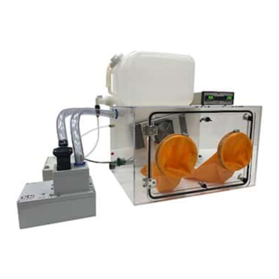
II. Description of Contents Item Description The Model 5504 is an acrylic (Plexiglas) chamber with dimensions of 24” W x 18” D x 15” H. The chamber features an 18” x 12” door opening and non-setting gasket. It is constructed... - Page 6 Tubing is included. *Temperature and Humidity range is valid for the M 5504 chamber with an ambient temperature of 22°C ±3°C and relative humidity of 25% to 70% RH. Lower humidities down to 2-5% RH can be achieved with increased temperatures and/or extended conditioning times.
- Page 7 *Temperature and Humidity range is valid for the M 5504 chamber with an ambient temperature of 22°C ±3°C and relative humidity of 25% to 70% RH. Lower humidities down to 2-5% RH can be achieved with increased temperatures and/or extended conditioning times.
-
Page 8: Set-Up Guide
III. Set-Up Guide TOOLS NEEDED: Part 1: Chamber Unpacking and Initial Setup Step 1-1 Step 1-2 Step 1-3 Note: DO NOT use any of Place the chamber on a clean, level Unpack the accessories and the chamber fittings or the bench area. -
Page 9: Part 2: Operating System Setup
Part 2: Operating System Setup Part 2a. Controller: Model 5000-Series Microcontroller with 556 Sensor Step 2a-1 Step 2a-2 Step 2a-3 Place the controller in an accessible, On the rear of the controller unit, Ensure the sensor and its cable are ensure the “POWER”... -
Page 10: Part 2C. Humidification: Model 5482 Ultrasonic Humidifier
Step 2b-4 Step 2b-5 Locating the Power Supply (2), plug After verifying the fans turn on, the the AC power cable from the Power power cord may be unplugged from Supply into a standard wall outlet. the AC outlet until the entire setup is complete and the chamber is The thermoelectric fans will turn on intended to be used. - Page 11 Step 2c-4 Step 2c-5 Step 2c-6 Fill the tank to intended level, up to Place water tank at a height above Ensure the drain valve on the humidifier unit is set to the “OFF” five gallons, with de-ionized or the humidifier. distilled water only.
- Page 12 Step 2c-10 Step 2c-11 Step 2c-12 Concluding the humidifier function Locate the two barb fittings on the Ensure the Light Blue/Cyan color- test, plug the three-prong humidifier top-left of the left chamber wall. The indicator ring is on the barb closer to AC line cord into the “HUMIDIFY”...
-
Page 13: Part 2D. Dehumidification Systems
Part 2d. Dehumidification Systems Multiple dehumidification operating systems are available for purchase, depending on preference and available lab amenities. Options include the Model 5461 Molecular Sieve, the Model 5465 Dry Nitrogen Valve, and the Model 5478 Regenerating Desiccant System. Information on each of these systems can be found at www.electrotechsystems.com/product-category/environmental-control/operating-systems/. - Page 14 Step 2d-4 (M 5461) Step 2d-5 (M 5461) Step 2d-6 (M 5461) With the rest of the semi-rigid tubing, With the remaining portion of the Plug the three-prong dehumidifier AC line cord into the “DEHUMIDIFY” push one end of the tubing firmly into semi-rigid tubing, push one end of the “AIR INPUT”...
- Page 15 Step 2d-4 (M 5465) Step 2d-5 (M 5465) Step 2d-6 (M 5465) Plug the two-prong AC power cable Plug the 3-prong AC power cable Ensure the flexible tubing is securely located on the M 5465 valve into the located on the over-pressure monitor connected to both the over-pressure into the “DEHUMIDIFY”...
- Page 16 Step 2d-4 (M 5478) Step 2d-5 (M 5478) Step 2d-6 (M 5478) Plug the remaining M 5478 3-prong Plug the 3-prong AC power cable Ensure the flexible tubing is securely power cable (on the left) into the located on the over-pressure monitor connected to both the over-pressure “Valve Power”...
-
Page 17: Quick Start Guide
IV. Quick Start Guide Step 1 – Turn on Controller Verify that the controller and each separate operating system is set up correctly as described in Section III. Set-Up Guide. With the sensor and operating systems plugged into the controller, turn the “POWER” switch on the back of the controller to the ON (I) position. -
Page 18: Functionality
V. Functionality Controller Front View Item Description Functionality Allows the user to manually enable or disable the “HUMIDIFY” Switch Humidification System. Pushing this switch to the (‘O’) is “Off” Allows the user to manually enable or disable the “DEHUMIDIFY” Switch Dehumidification System. - Page 19 Controller Rear View Item Description Functionality This switch disconnects all power to the controller and going “POWER” Switch to the chamber operating systems. “I” is on, “O” is off. Connect incoming AC power here. Socket accepts standard “POWER IN” Socket IEC power cable.
-
Page 20: Specifications
VI. Specifications Model 5504 Chamber Mechanical Humidification (if included) Material Clear and White Acrylic Ultrasonic Humidifier Model 5482 Internal Volume ~3.25 cu. Ft. (92L) RH% Max 100% 23.5”W x 17.25”D x 14.5”H RH% ramp 50% to 90% typ. < 10 minutes... - Page 21 The entire humidity range cannot be obtained at all temperatures due primarily to dew point considerations. The graph below depicts an approximation of achievable relative humidities at varying temperatures. D01833 Revision A – 20211101 www.electrotechsystems.com 833-ENV-GURU (833-368-4878)
-
Page 22: Repair And Maintenance
ETS recommends the Model 5000-Series controller and Model 556 Sensor be calibrated annually. Only the controller and sensor need to be returned for calibration, do not return the chamber. To return equipment to ETS for calibration it is first necessary to obtain a RMA number, please call 215-887-2196 or email service@ets2.com... -
Page 23: Repair
Refer to Section III. Set-Up Guide and Section IV. Quick Start Guide to return the humidifier to standard operation. Repair To return equipment to ETS for calibration it is first necessary to obtain a RMA number, please call 215-887-2196 or email service@ets2.com - Page 23 of 24 D01833 Revision A –... -
Page 24: Warranty
VIII. Warranty Limited Warranties. Seller warrants that all goods manufactured and delivered hereunder shall (a) conform to any samples, drawings, specifications, or other written documents provided to Seller by Buyer or approved by Buyer to Seller and (b) be free from all defects in workmanship and material.
Need help?
Do you have a question about the 5504 and is the answer not in the manual?
Questions and answers