
Subscribe to Our Youtube Channel
Related Manuals for Maxon ESCON 50/8


Summary of Contents for Maxon ESCON 50/8
- Page 1 Hardware Reference ESCON Module 50/8 Servo Controller | P/N 532872 & 586137 Hardware Reference CCMC | Edition 2020-06 | DocID rel9072...
-
Page 2: Table Of Contents
Table of Contents ABLE OF ONTENTS About About this Document..........3 About the Device. -
Page 3: About
About About this Document About About this Document 1.1.1 Intended Purpose The purpose of the present document is to familiarize you with the ESCON Module 50/8 Servo Controller. It will highlight the tasks for safe and adequate installation and/or commissioning. Follow the described instructions …... -
Page 4: Table 1-2 Symbols & Signs
About About this Document 1.1.4 Symbols & signs In the course of the present document, the following symbols and signs will be used. Type Symbol Meaning Indicates an imminent hazardous situation. DANGER If not avoided, it will result in death or serious injury. Indicates a potential hazardous situation. -
Page 5: About The Device
The present document – including all parts thereof – is protected by copyright. Any use (including reproduc- tion, translation, microfilming, and other means of electronic data processing) beyond the narrow restric- tions of the copyright law without the prior approval of maxon, is not permitted and subject to prosecution under the applicable law. -
Page 6: About The Safety Precautions
– and be kept – in a safe operating mode. • Be aware that you are not entitled to perform any repair on components supplied by maxon. Electrostatic Sensitive Device (ESD) •... -
Page 7: Specifications
Specifications Technical Data Specifications Technical Data ESCON Module 50/8 (532872) ESCON Module 50/8 HE (586137) Nominal operating voltage +V 10…50 VDC Absolute operating voltage 8 VDC/56 VDC CC min CC max 0.98 x +V Output voltage (max.) Output current I (<20 s) 8 A/15 A cont... - Page 8 Specifications Technical Data ESCON Module 50/8 (532872) ESCON Module 50/8 HE (586137) Module 50/8 approx. 16 g Weight Module 50/8 HE approx. 84 g Module 50/8 53.3 x 37.5 x 14.5 mm Physical Dimensions (L x W x H) Module 50/8 HE 53.3 x 37.5 x 30.6 mm Plugs into socket headers with 2.54 mm pitch and M2.5 Connection...
-
Page 9: Thermal Data
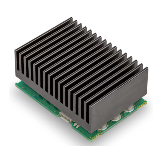
Specifications Thermal Data Thermal Data 2.2.1 Power Dissipation and Efficiency The servo controller is available in two variants – as «ESCON Module 50/8 HE» (586137) with heat sink and as «ESCON Module 50/8» (532872) without heat sink. The two following graphs can be used to determine the application limits for output current and ambient temperature for different supply voltages. -
Page 10: Limitations
°C (Y-axis) a heat sink with a maximum heat resistance R of less than 4 K/W is required (yel- low characteristic). Use the maxon accessory «ESCON Module 50/8 Thermal Pad» (586142) for optimum heat transfer and observe the manufacturer's specifications for the respective heat sink. Specification / Accessories Dimensions 53.3 x 37.5 x 16.5 mm (L x B x H) -
Page 11: Dimensional Drawings
Specifications Dimensional Drawings Dimensional Drawings Figure 2-3 ESCON Module 50/8 – Dimensional Drawing [mm] Figure 2-4 ESCON Module 50/8 HE – Dimensional Drawing [mm] ESCON Module 50/8 Hardware Reference 2-11 CCMC | 2020-06 | rel9072... -
Page 12: Standards
Specifications Standards Standards The described device has been successfully tested for compliance with the below listed standards. In prac- tical terms, only the complete system (the fully operational equipment comprising all individual components, such as motor, servo controller, power supply unit, EMC filter, cabling etc.) can undergo an EMC test to ensure interference-free operation. -
Page 13: Setup
Setup Generally applicable Rules Setup MPORTANT OTICE REREQUISITES FOR ERMISSION TO COMMENCE NSTALLATION The ESCON Module 50/8 is considered as partly completed machinery according to EU Directive 2006/42/ EC, Article 2, Clause (g) and is intended to be incorporated into or assembled with other machinery or other partly completed machinery or equipment. -
Page 14: Configuration Of Power Supply
Setup Configuration of Power Supply Configuration of Power Supply Basically, any power supply may be used, provided it meets the minimal requirements stated below. Power Supply Requirements 10…50 VDC Output voltage Absolute output voltage min. 8 VDC; max. 56 VDC Depending on load Output current •... -
Page 15: Connections
Setup Connections Connections The actual connection will depend on the overall configuration of your drive system and the type of motor you will be using. Follow the description in the given order and choose the wiring diagram that best suits the components you are using. -
Page 16: Figure 3-5 Pin Assignment
Setup Connections Figure 3-6 Pin Assignment Signal Description DigIN/DigOUT4 Digital input/output 4 DigIN/DigOUT3 Digital input/output 3 DigIN2 Digital input 2 DigIN1 Digital input 1 Ground AnOUT2 Analog output 2 AnOUT1 Analog output 1 AnIN2− Analog input 2, negative signal AnIN2+ Analog input 2, positive signal AnIN1−... -
Page 17: Figure 3-7 Hall Sensor 1 Input Circuit (Analogously Valid Also For Hall Sensors 2 & 3)
Setup Connections 3.3.2 Hall Sensor Hall sensor supply voltage +5 VDC Max. Hall sensor supply current 30 mA Input voltage 0…24 VDC Max. input voltage +24 VDC Logic 0 typically <1.0 V Logic 1 typically >2.4 V Internal pull-up resistor 10 kΩ... -
Page 18: Figure 3-8 Encoder Input Circuit Ch A "Differential" (Analogously Valid Also For Ch B)
Setup Connections 3.3.3 Encoder Best practice • Differential signals offer good resistance against electrical interference. Therefore we recommend using a differential scheme. Nevertheless, the controller supports both schemes – differential and sin- gle-ended (unsymmetrical). • The controller does not require an index impulse (Ch I, Ch I\). •... -
Page 19: Figure 3-9 Encoder Input Circuit Ch A "Single-Ended" (Analogously Valid Also For Ch B)
Setup Connections Single-ended Input voltage 0…5 VDC Max. input voltage +12 VDC/−12 VDC Logic 0 <1.0 V Logic 1 >2.4 V = typically +420 μA @ 5 V Input high current = typically −170 μA @ 0 V Input low current Max. -
Page 20: Figure 3-10 Digin1 Circuit
Setup Connections 3.3.4 Digital I/Os 3.3.4.1 Digital Input 1 Input voltage 0…36 VDC Max. input voltage +36 VDC/−36 VDC Logic 0 typically <1.0 V Logic 1 typically >2.4 V typically 47 kΩ (<3.3 V) Input resistance typically 38.5 kΩ (@ 5 V) typically 25.5 kΩ... -
Page 21: Figure 3-11 Digin2 Circuit
Setup Connections 3.3.4.2 Digital Input 2 Input voltage 0…36 VDC Max. input voltage +36 VDC/−36 VDC Logic 0 typically <1.0 V Logic 1 typically >2.4 V typically 47 kΩ (<3.3 V) Input resistance typically 38.5 kΩ (@ 5 V) typically 25.5 kΩ (@ 24 V) Input current at logic 1 typically 130 µA @ +5 VDC Switching delay... -
Page 22: Figure 3-13 Digout3 Circuit (Analogously Valid Also For Digout4)
Setup Connections DigOUT Max. input voltage +36 VDC Max. load current 500 mA Max. voltage drop 0.5 V @ 500 mA Max. load inductance 100 mH @ 24 VDC; 500 mA Figure 3-13 DigOUT3 Circuit (analogously valid also for DigOUT4) Figure 3-14 DigOUT3 Wiring Examples (analogously valid also for DigOUT4) ESCON Module 50/8 Hardware Reference... -
Page 23: Figure 3-15 Anin1 Circuit (Analogously Valid Also For Anin2)
Setup Connections 3.3.5 Analog I/Os 3.3.5.1 Analog Inputs 1 and 2 Input voltage −10…+10 VDC (differential) Max. input voltage +24 VDC/−24 VDC Common mode voltage −5…+10 VDC (referenced to GND) 80 kΩ (differential) Input resistance 65 kΩ (referenced to GND) A/D converter 12-bit Resolution... -
Page 24: Figure 3-17 Usb Socket J7
Setup Connections 3.3.6 USB (J7) Hot plugging the USB Interface may cause Hardware Damage If the USB interface is being hot-plugged (connecting while the power supply is on), the possibly high differ- ences in potential of the two power supplies of controller and PC/Notebook can lead to damaged hardware. •... - Page 25 Setup Connections USB standard USB 2.0 / USB 3.0 (full speed) Max. bus operating voltage +5.25 VDC Typical input current 60 mA Max. DC data input voltage −0.5…+3.8 VDC ESCON Module 50/8 Hardware Reference 3-25 CCMC | 2020-06 | rel9072...
-
Page 26: Status Indicators
Setup Status Indicators Status Indicators Light-emitting diodes (LEDs) indicate the actual operating status (green) and possible errors (red). Figure 3-18 LEDs – Location Status/Error Green INIT slow DISABLE ENABLE STOPPING; STOP STANDSTILL • +Vcc Overvoltage Error ERROR • +Vcc Undervoltage Error •... -
Page 27: Wiring
Figure 4-19 Interfaces – Designations and Location Note The subsequent diagrams feature this symbol: • Ground safety earth connection (optional) DC Motors MAXON MOTOR Figure 4-20 maxon DC motor ESCON Module 50/8 Hardware Reference 4-27 CCMC | 2020-06 | rel9072... -
Page 28: Figure 4-21 Maxon Dc Motor With Dc Tacho
Wiring DC Motors DC T MAXON MOTOR WITH ACHO Figure 4-21 maxon DC motor with DC Tacho ESCON Module 50/8 Hardware Reference 4-28 CCMC | 2020-06 | rel9072... -
Page 29: Figure 4-22 Maxon Dc Motor With Encoder
Wiring DC Motors MAXON MOTOR WITH NCODER Figure 4-22 maxon DC motor with Encoder ESCON Module 50/8 Hardware Reference 4-29 CCMC | 2020-06 | rel9072... -
Page 30: Ec Motors
Wiring EC Motors EC Motors MAXON MOTOR WITH ENSORS Figure 4-23 maxon EC motor with Hall Sensors ESCON Module 50/8 Hardware Reference 4-30 CCMC | 2020-06 | rel9072... -
Page 31: Figure 4-24 Maxon Ec Motor With Hall Sensors & Encoder
Wiring EC Motors & E MAXON MOTOR WITH ENSORS NCODER Figure 4-24 maxon EC motor with Hall Sensors & Encoder ESCON Module 50/8 Hardware Reference 4-31 CCMC | 2020-06 | rel9072... - Page 32 Wiring EC Motors • • p a g e i n t e n t i o n a l l y l e f t b l a n k • • ESCON Module 50/8 Hardware Reference 4-32 CCMC | 2020-06 | rel9072...
-
Page 33: Motherboard Design Guide
If you are not trained in the design and development of printed circuit boards, you will need additional sup- port for this point. maxon will be happy to provide you with a quote for designing and manufacturing a motherboard for your specific application. -
Page 34: Requirements For Components Of Third-Party Suppliers
Motherboard Design Guide Requirements for Components of Third-party Suppliers Requirements for Components of Third-party Suppliers 5.1.1 Socket Headers The ESCON Module 50/8’s implementation with pin headers permits mounting in two different ways. The module can either be plugged onto a socket header (Table 5-13) or be directly soldered to a printed cir- cuit board. -
Page 35: Figure 5-26 Wiring Of Motor Winding 1 (Analogously Valid Also For Motor Windings 2 & 3)
The below wiring examples refer to addi- tional inductances of 4.7 μH and 22 μH. If a different additional inductance is required, also the filter compo- nents must be adapted accordingly. Should you need further help with the filter design, contact maxon Sup- port at http://support.maxongroup.com. -
Page 36: Table 5-13 Motherboard Design Guide - Recommended Components
Motherboard Design Guide Requirements for Components of Third-party Suppliers 5.1.4 Recommended Components and Manufacturers Recommended components Straight socket header, pluggable with 0.64 x 0.64 mm pin headers, 2.54 mm pitch, contact material: gold Socket Samtec (SSW-109-01-L-D) 9 poles, 2 rows Header Samtec (SSW-109-01-G-D) Samtec (SSW-111-01-L-S) -
Page 37: Design Guidelines
Motherboard Design Guide Design Guidelines Design Guidelines The following instructions are intended to serve as an aid for designing an application-specific motherboard and ensuring the correct and reliable integration of the ESCON Module 50/8. 5.2.1 Ground All ground connections (GND) should be internally connected to the ESCON Module 50/8 (equal potential). It is customary to equip the motherboard with a ground plane. -
Page 38: Pin Assignment
Motherboard Design Guide Pin Assignment Pin Assignment For detailed specifications chapter “3.3 Connections” on page 3-15. Technical Data For detailed specifications chapter “2 Specifications” on page 2-7. Dimensional Drawing For the dimensional drawing Figure 2-3 on page 2-11. ESCON Module 50/8 Motherboard (586048) As an alternative to the development of a motherboard the «ESCON Module 50/8 Motherboard»... -
Page 39: Figure 5-30 Escon Module 50/8 Mobo - Mounting On Din Rail
Motherboard Design Guide ESCON Module 50/8 Motherboard (586048) 5.7.1 Assembly The ESCON Module 50/8 MoBo is designed to easily be screw-mounted or integrated into standard rail sys- tems. For ordering information for the components required Figure 5-30 (only for illustrative purposes) and Table 5-15. -
Page 40: Figure 5-31 Escon Module 50/8 Mobo - Power Plug J1
Motherboard Design Guide ESCON Module 50/8 Motherboard (586048) 5.7.2 Connections Note The USB interface is located directly at the ESCON Module 50/8. 5.7.2.1 Power Supply (J1) Figure 5-31 ESCON Module 50/8 MoBo – Power Plug J1 Signal Description Power_GND Ground of operating voltage Nominal operating voltage (+10…+50 VDC) Table 5-16 ESCON Module 50/8 MoBo –... -
Page 41: Figure 5-32 Escon Module 50/8 Mobo - Motor Plug J2
Motherboard Design Guide ESCON Module 50/8 Motherboard (586048) 5.7.2.2 Motor (J2) The servo controller is set to drive either maxon DC motors (brushed) or maxon EC motors (brushless). Figure 5-32 ESCON Module 50/8 MoBo – Motor Plug J2 Signal Description... -
Page 42: Figure 5-33 Escon Module 50/8 Mobo - Hall Sensor Plug J3
Motherboard Design Guide ESCON Module 50/8 Motherboard (586048) 5.7.2.3 Hall sensor (J3) Suitable Hall effect sensors IC use «Schmitt trigger» with open collector output. Figure 5-33 ESCON Module 50/8 MoBo – Hall Sensor Plug J3 Signal Description Hall sensor 1 Hall sensor 1 input Hall sensor 2 Hall sensor 2 input... -
Page 43: Figure 5-34 Escon Module 50/8 Mobo - Encoder Socket J4
Motherboard Design Guide ESCON Module 50/8 Motherboard (586048) 5.7.2.4 Encoder (J4) Figure 5-34 ESCON Module 50/8 MoBo – Encoder Socket J4 Signal Description not connected – +5 VDC Encoder supply voltage (+5 VDC; 70 mA) ≤ Ground not connected – Channel A\ Channel A complement Channel A... -
Page 44: Table 5-25 Escon Module 50/8 Mobo - Encoder Cable
Motherboard Design Guide ESCON Module 50/8 Motherboard (586048) Encoder Cable (275934) Cable cross-section 10 x AWG28, round-jacket, twisted pair flat cable, 1.27 mm pitch Length 3.20 m Head A DIN 41651 female, 2.54 mm pitch, 10 pins, with strain relief Head B DIN 41651 connector, 2.54 mm pitch, 10 poles, with strain relief Table 5-25... -
Page 45: Figure 5-35 Escon Module 50/8 Mobo - Digital I/Os Plug J5
Motherboard Design Guide ESCON Module 50/8 Motherboard (586048) 5.7.2.5 Digital I/Os (J5) Figure 5-35 ESCON Module 50/8 MoBo – Digital I/Os Plug J5 Signal Description DigIN1 Digital input 1 DigIN2 Digital input 2 DigIN/DigOUT3 Digital input/output 3 DigIN/DigOUT4 Digital input/output 4 Ground +5 VDC Auxiliary output voltage (+5 VDC;... -
Page 46: Figure 5-36 Escon Module 50/8 Mobo - Analog I/Os Plug J6
Motherboard Design Guide ESCON Module 50/8 Motherboard (586048) 5.7.2.6 Analog I/Os (J6) Figure 5-36 ESCON Module 50/8 MoBo – Analog I/Os Plug J6 Signal Description AnIN1+ Analog input 1, positive signal AnIN1− Analog input 1, negative signal AnIN2+ Analog input 2, positive signal AnIN2−... -
Page 47: Figure 5-37 Escon Module 50/8 Mobo - Maxon Dc Motor (J2)
Note The subsequent diagrams feature this symbol: • Ground safety earth connection (optional) 5.7.3.1 DC Motors MAXON MOTOR Figure 5-37 ESCON Module 50/8 MoBo – maxon DC motor (J2) ESCON Module 50/8 Hardware Reference 5-47 CCMC | 2020-06 | rel9072... -
Page 48: Figure 5-38 Escon Module 50/8 Mobo - Maxon Dc Motor With Dc Tacho (J2)
Motherboard Design Guide ESCON Module 50/8 Motherboard (586048) DC T MAXON MOTOR WITH ACHO Figure 5-38 ESCON Module 50/8 MoBo – maxon DC motor with DC Tacho (J2) ESCON Module 50/8 Hardware Reference 5-48 CCMC | 2020-06 | rel9072... -
Page 49: Figure 5-39 Escon Module 50/8 Mobo - Maxon Dc Motor With Encoder (J2 / J4)
Motherboard Design Guide ESCON Module 50/8 Motherboard (586048) MAXON MOTOR WITH NCODER Figure 5-39 ESCON Module 50/8 MoBo – maxon DC motor with Encoder (J2 / J4) ESCON Module 50/8 Hardware Reference 5-49 CCMC | 2020-06 | rel9072... - Page 50 Motherboard Design Guide ESCON Module 50/8 Motherboard (586048) 5.7.3.2 EC motors MAXON MOTOR WITH ENSORS Figure 5-40 ESCON Module 50/8 MoBo – maxon EC motor with Hall Sensors (J2 / J3) ESCON Module 50/8 Hardware Reference 5-50 CCMC | 2020-06 | rel9072...
- Page 51 ESCON Module 50/8 Motherboard (586048) & E MAXON MOTOR WITH ENSORS NCODER Figure 5-41 ESCON Module 50/8 MoBo – maxon EC motor with Hall Sensors & Encoders (J2 / J3 / J4) ESCON Module 50/8 Hardware Reference 5-51 CCMC | 2020-06 | rel9072...
-
Page 52: Spare Parts
Motherboard Design Guide Spare Parts Spare Parts Order number Description 444144 2-pole pluggable screw-type terminal block, 3.5 mm pitch, labeled 1…2 444145 4-pole pluggable screw-type terminal block, 3.5 mm pitch, labeled 1…4 444146 5-pole pluggable screw-type terminal block, 3.5 mm pitch, labeled 1…5 444147 6-pole pluggable screw-type terminal block, 3.5 mm pitch, labeled 1…6 444148... - Page 53 ESCON Module 50/8 MoBo – maxon DC motor with Encoder (J2 / J4) ......
- Page 54 ESCON Module 50/8 MoBo – maxon EC motor with Hall Sensors (J2 / J3) ......
- Page 55 ESCON Module 50/8 MoBo – Power Plug J1 – Specification & Accessories ......40 Table 5-18 ESCON Module 50/8 MoBo – Motor Plug J2 – Pin Assignment for maxon DC motor (brushed) ..41 Table 5-19 ESCON Module 50/8 MoBo –...
- Page 56 Index NDEX additionally applicable regulations 6 operating license 13 analog inputs 23 operating status, display 26 applicable EU directive 13 order numbers 275934 44 assignment of the connections 15 403968 24 444144 52 444145 52 cables (prefab) 444146 52 Encoder Cable 44 444147 52 USB Type A - micro B Cable 24 444148 52...
- Page 57 Index USB interface 24 wiring diagrams for DC motors 27 EC motors 30 ESCON Module 50/8 Hardware Reference Z-57 CCMC | 2020-06 | rel9072...
- Page 58 The present document – including all parts thereof – is protected by copyright. Any use (including reproduction, translation, micro- filming, and other means of electronic data processing) beyond the narrow restrictions of the copyright law is not permitted with- out the prior approval of maxon and will be subject to prosecution under the applicable law. maxon motor ag Brünigstrasse 220...
Need help?
Do you have a question about the ESCON 50/8 and is the answer not in the manual?
Questions and answers