BobsCNC Evolution 4 Assembly Instructions Manual
Upgrade kit
Hide thumbs
Also See for Evolution 4:
- Assembly manual (139 pages) ,
- Assembly instructions manual (39 pages)

Related Manuals for BobsCNC Evolution 4


Summary of Contents for BobsCNC Evolution 4
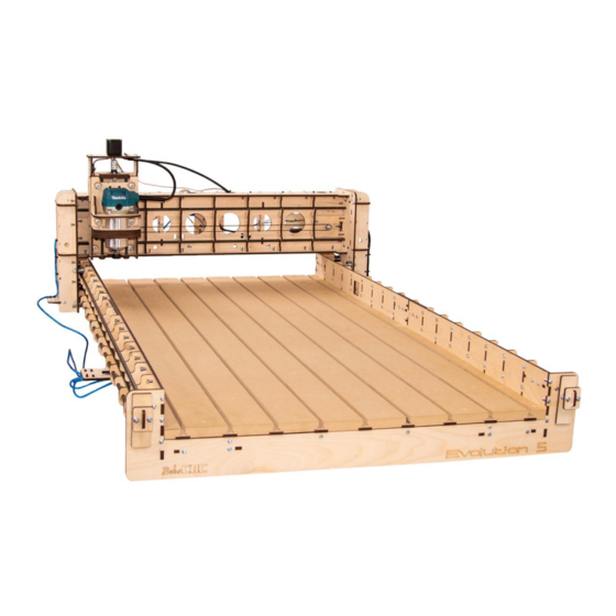
- Page 1 Evolution 4 Upgrade Kit Converts the Evolution 4 CNC Router into an Evolution 5 CNC Router Assembly Instructions Rev. 1.9...
-
Page 2: Table Of Contents
T-Slot Spoilboard ................................. 39 Wood Components ..............................39 Required Hardware ..............................39 Illustrated Step by Step Instructions ........................ 40 Updating Firmware ..............................49 Evolution 4 Extension Firmware Value Change .................... 49 Appendix ($130=1283) .............................. 50 Evolution 4 Firmware Values ..........................50... -
Page 3: Evolution 4 Upgrade Specifications
EVOLUTION 4 Upgrade Specifications The Assembled Footprint: Length: 58.7" (1490 mm) Width: 39" (994 mm) Height: 20.9" (530 mm) Assembled Weight: 48 lbs. Cutting Area: 50.5" (1283 mm) 24" (610 mm) 3.3" (85 mm) -
Page 4: Information/Warning Boxes
Safety is the First Priority. Always wear proper protective equipment and use "safety sense" when assembling and operating your Evolution CNC Router. Information/Warning Boxes CAUTION Indicates a possible risk of injury that can result from failure to follow this instruction WARNING Indicates the possible damage to the machine, its components, the work... -
Page 5: Safety Precautions And Warnings
Safety Precautions and Warnings Evolution Series CNC Routers have a 110 v. power supply and use bits that spin at 28,000 rpm with cutting edges that are sharp and hazardous. The operator must understand the potential hazards and is responsible to take appropriate safety precautions before operating the Router. -
Page 6: Getting Started
Getting Started Required Tools: A pair of long nose pliers. Diagonal Cutters or sharp knife to trim nylon ties. Calipers or measuring tape to measure part placement. #3 Phillips screwdriver to build the main components. 220 grit sandpaper to remove laser marks on wood pieces (if desired). LOCTITE 242™... - Page 7 Try using strips of 1inch blue painters’ tape behind the T-Slots to help hold the Nuts in place during assembly. Lock Nuts are never used to secure components that have T-Slots. They are only used to mount components where the Nut is not held in a Slot.
-
Page 8: Removing Components
Removing Components: Illustrated Step by Step Instructions Before you can upgrade your Evolution 4 you will need to remove several components. Step 1 Remove and discard Spoilboard. - Page 9 Step 2 Remove and discard Belts by first loosening the Belt Tensioner. Be sure to keep the Belt Retainers.
- Page 10 Step 3 Remove front Frame End Support and discard. Step 4 Remove both sides of the front Frame Corner Supports and set aside. They will be reinstalled with the new Evolution 5 End Support.
- Page 11 Step 5 Remove both sides of the Frame Corner Braces and set aside to be used in the Front Assembly. Save these parts Step 6 Clip and remove the Zip Ties that secure the USB Cable and Power Cords to the Wire Harness Supports.
- Page 12 Step 7 Slide Gantry Assembly off the Rails and carefully set it aside. Step 8 Remove the four X Rails and discard. The X frame will form the Rear Assembly.
-
Page 13: Frame Extension Assembly
X Frame Extension Assembly Wood Components Part # Description Photo Rail Support Frame Mid Support Extension Frame Mid Support Extension Frame Side Support Frame End Support Wire Harness Support Coupling EX12 Plate... -
Page 14: Hardware
Hardware Part # Description Photo M4 x 16 Machine Screw M4 Nut M4 Locknut GT2 Belts Stress Proof Steel X Rail... -
Page 15: Illustrated Step By Step Instructions
Illustrated Step by Step Instructions Step 1 The X Frame consists of a front and rear Assembly. To build the Front Assembly: Align the tabs of the Rail Supports (X1) into the slots in the Extension Frame Side Support (EX5). Secure with three M4 x 16 Machine Screws and Nuts for each Rail Support as shown. - Page 16 Step 2 Align the tabs of two Frame Corner Supports (previously removed) into the lower slots of the Frame Side Assembly and secure with two M4 x 16 Machine Screws and Nuts as shown. Repeat to complete the second Frame Side Assembly. Left Side Right Side Step 3...
- Page 17 Completed Front Side Assemblies...
- Page 18 Step 4 Align the slots in one of the Frame Side Assemblies with the tabs in the Frame Mid Support(X4) as shown and secure with two M4 x 16 Screws and Nuts. Inside View Outside View...
- Page 19 Step 5 Repeat the process until three Frame Mid Supports have been installed and secured. Step 6 Repeat this procedure to install the remaining Side Support Assembly.
- Page 20 Step 7 Align the slots in the X6 Frame End Support with the tabs in the Front X Frame Assembly and secure each side with six M4 x 16 Screws and Nuts. Completed Front X Frame Assembly...
- Page 21 Step 8 Using the Extension Frame Mid Support (EX4), align the tabs of the Wire Harness Support (X7) with the slots and secure with two M4 x 16 Machine Screws and Nuts for each end as shown. Align and mount the Frame Mid Support (X4) to the Mid Frame Assembly.
-
Page 22: Final Assembly
Final Assembly Illustrated Step by Step Instructions Step 1 Align the tabs of the Mid Frame Assembly into the slots of the Coupling Plate (EX12) (one for each Side of the Mid Frame Assembly) and press them together as shown. - Page 23 Step 2 Align the mounting holes of the Coupling Plates(EX12) with the holes in the Front X Frame Assembly. The ends of the Front X Frame Assembly will fit between the Coupling Plates.
- Page 24 Step 3 Insert the tabs of the Frame Mid Support (X4) into the slots of the Front X Frame Assembly and secure with four M4 x 16 Machine Screws and Locking Nuts for each side as shown.
- Page 25 Step 4 Align the unused mounting holes of the Coupling Plate with the holes in the Rear X Frame Assembly. The ends of the Rear X Frame Assembly will fit between the Coupling Plates. Secure each side with four M4 X 16 Screws and Lock Nuts.
- Page 26 IMPORTANT NOTE: Before tightening the Lock Nuts, hold a straight edge across the top each side. Make sure the top edges of the entire X Frame Assembly are flat when tightening. Completed Frame Assembly...
- Page 27 Step 5 Insert each of the 4 X Rails starting from one end while moving through each support. Note: rotating the rod gently will ease installation. Step 6 Carefully reinstall the Gantry Assembly. In the photos below the Gantry is resting on a piece of ¾” scrap to help hold the bearings up before installing the new Rails.
- Page 28 Step 7 Carefully install the two X Rails through the X Frame Assembly Support and the Rail Supports. Lift one side of the Gantry to allow the Rail to pass beneath the upper bearing. Step 8 Carefully install the lower Rails through the X Frame Assembly and the Rail Supports threading the rail to pass over the lower bearing.
- Page 29 Step 9 Adjusting the Eccentric Spacers Clockwise Counterclockwise NOTE: To raise the SG20U Bearing against the Rail on the Left Side, use a 13mm wrench or socket to rotate the Eccentric Adjustment Spacer clockwise. To raise the Bearing on the Right Side, rotate the Eccentric Adjustment Spacer counterclockwise.
- Page 30 Raise the left lower Bearing to the corresponding mark. Using your fingers try to turn the left lower Bearing. The Bearing should only move if the Gantry moves. Once the Bearings are snug against the Rail, tighten the Locknut with a 10mm wrench and Phillips Head screwdriver as shown. NOTE: There are access holes located at the bottom of the...
- Page 31 Step 10 Installing the X GT2 Belts. Cut two of the GT2 Belts to a length of 60 7/8 inches. Insert one end of the Belt into the Short Belt Retainer (previously removed). Next, thread the free end of the GT2 Belt through the Rail Stop (previously removed).
- Page 32 Insert the Belt Retainer and Belt into and through the Rail Stop. Then insert the Assembly into the bottom slot at the back of the X Frame Assembly. NOTE: Using a Zip Tie, snug the belt in the Retainer. Make sure the square lock of the Zip Tie is located on the top of the Belt Retainer.
- Page 33 Route the free end of the Belt through the Gantry. Note: Slide the Gantry Assembly in front of the square access hole in the X Frame. This opening provides the access you need to loop the Belt around the Idler and Flange Bearings. We suggest that you watch the short video demonstrating how to correctly route and install the Belts around the Flange and Idler Bearings.
- Page 34 The following photos illustrate the proper path for routing the Belt. The photos were taken before the Gantry was installed on the X Frame for Illustration purposes only! The Gantry Assembly must be installed on the X Frame Assembly before attempting to install the Belts.
- Page 35 Loop the Belt over the Belt Pulley so that the Belt teeth engage the teeth of Pulley. Finished Belt Routing viewed through the access port. Repeat to install the other X Belt.
- Page 36 Step 11 Securing the X1 and X2 Belts Insert two M6 x 30 Machine Screws through the Belt Adjustment Plate (previously removed) and secure with a M6 Nut. Add one M6 Nut to each Machine Screw as shown. Insert the Long Belt Retainer (previously removed) through the Belt Adjusting Plate into the Rail Stop (previously removed) as shown.
- Page 37 Insert the Belt Tightening Assembly into the upper slot of the X Assembly as shown. At the front of the machine be sure to insert in the upper slot. Insert the end of the Belt into the Belt Retainer. Be sure to seat the Belt completely in the Retainer as...
- Page 38 Step 12 Tighten the X1 and X2 Belts. Make sure the Nut closest to the Belt Adjusting Plate is tight. Using a 10mm wrench, hold the adjustment Nut and turn the machine screw to tighten the Belt. Be sure to adjust both Screws the same amount until the Belt is tight.
- Page 39 Step 13 Secure the USB Cable to the underside of the Wire Harness with Zip Ties as shown. Step 14 Secure the Power Cords to the underside of the Wire Harness with Zip Ties as shown.
-
Page 40: T-Slot Spoilboard
T-Slot Spoilboard Wood Components Part # Description Photo Fastening Strip T-Slot Small Board T-Slot Large Board Spacer Strips (set) Required Hardware Part # Description Photo 1.25” Woodscrews M4 X 16 Machine Screws M4 Square Nuts... -
Page 41: Illustrated Step By Step Instructions
The Mid Frame and End Supports of the old version Evolution 4 does not have predrilled holes for attaching Mounting Strips. Mounting strips can be made using five 1”x 2” furring strips. Illustrated Step by Step Instructions Step 1 NOTE: For newer kits, skip this Step and Step 2 For the old version use a new Fastening Strip(SB1) as a template to mark the location of mounting holes. - Page 42 Step 2 NOTE: For newer kits, skip Step 1 and this Step. Cut one 17- inch and four 28-inch long pieces of 1 x 2 stock (not included). These will serve as battens that you can screw into to secure your spoilboard.
- Page 43 Step 3 NOTE: For newer kits, start this Step Insert four M4 Square Nuts into each of the T-Slots in the SB1 Fastening Strip. Step 4 Lay a T Slot Small Board (SB3) on the X Frame Assembly with the cut mark facing up. The position of the predrilled holes (circled below) in the strip will indicate the side on which the Fastening Strips (SB1) will be mounted.
- Page 44 Step 5 Carefully align the T-Slots in the Fastening Strips with the mounting holes in the Rail Supports and secure with four M4 x 16 Screws. Make sure the Fastening Strip is mounted on the inside of the X Frame Front. Before tightening, make sure the Fastening Strips are mounted so that the X Frame Supports are approximately 1/16”...
- Page 45 Step 6 Repeat to install the next fastening strip until all eleven strips are installed.
- Page 46 Step 7 Before installing the Spoilboard, it is important to make sure the X Frame is square. The simplest way to do this is to measure diagonally from one corner of the cutting area to the other. If the measurements are exactly the same, the X-Frame is square. If not, gently rack the Frame until the measurements are equal.
- Page 47 Step 9 Install the T-Slot Small Board (SB3) along the left side of the X Frame Assembly with the notch facing down as shown. Next, install the Spacer Strip Assembly so that it lies beneath the bottom notch of the T-Slot Board. Step 10 Repeat, using T-Slot Large Board (SB4), making sure the notch is fully seated on top of the...
- Page 48 Step 11 Make sure the T Slot Small Boards are tight against each side. Then using the 1¼ inch Wood Screws, secure the Spoilboard to the X-Frame Assembly. We recommend counter sinking the wood screws approx. 3/16” below the surface of the T-Slot Boards.
- Page 49 Finished View...
-
Page 50: Updating Firmware
Updating Firmware Evolution 4 Extension Firmware Value Change Connect the CNC to the USB and connect to UGS Platform. Type in $130=1283 in the command textbox of the console window of UGS and press the enter key. This will change the soft limit for the X axis to the new value of 1283mm (50.5”) -
Page 51: Appendix ($130=1283)
Appendix ($130=1283) Evolution 4 Firmware Values Value Description (step pulse, usec) (step idle delay, msec) (step port invert mask:00000000) (dir port invert mask:00000000) (step enable invert, bool) (limit pins invert, bool) (probe pin invert, bool) (status report mask:00000011) 0.01 (junction deviation, mm) 0.002... - Page 52 $111 10000 (y max rate, mm/min) $112 2000 (z max rate, mm/min) $120 (X-axis acceleration, mm/sec^2) $121 (Y-axis acceleration, mm/sec^2) $122 (Z-axis acceleration, mm/sec^2) $130 1283 (X-axis maximum travel, millimeters) $131 (Y-axis maximum travel, millimeters) $132 (Z-axis maximum travel, millimeters)
Need help?
Do you have a question about the Evolution 4 and is the answer not in the manual?
Questions and answers