Table of Contents
Advertisement
Advertisement
Table of Contents

Subscribe to Our Youtube Channel
Related Manuals for BobsCNC Evolution Series


Summary of Contents for BobsCNC Evolution Series
- Page 1 Evolution 4 Assembly Manual Rev. 1.06...
- Page 2 Welcome to the Family. We’re excited that you purchased the Evolution 4 CNC Router Kit from BobsCNC, and we know you’re just as excited to put it together. This manual gives you step by step instructions to ensure your success in assembling the Evolution 4 CNC Router and provides all the information you need to get your machine up and running.
-
Page 3: Table Of Contents
Table of Contents Information/Warning Boxes ............................5 Safety Precautions and Warnings ..........................6 Getting Started ................................. 7 Required Tools: ................................7 To Operate the EVOLUTION 4 CNC Router, you need will need:............. 7 Recommended for the electronic setup include: ................... 7 Assembly Recommendations: ............................ - Page 4 Required Hardware ..............................91 Illustrated Step by Step Instructions ........................ 93 Spoilboard installation (optional) ........................126 Completed Views ............................... 128 Tramming ..................................133 Congratulations! You Just Completed the Assembly of Your Evolution 4........... 135 Appendix ..................................136 Evolution 4 Firmware Values ..........................136 Evolution Washer Dimensions ..........................
- Page 5 EVOLUTION 4 Specifications Laser cut 6mm Baltic Birch Frame components. Fully Engineered Frame with rigid Box and Beam Gantry. Fully supported 5/16-inch stress proof steel Rails with SG20U Bearings. GT2 Belt Drive on X and Y axis. 2 mm pitch, 4 start Acme Threaded Rod on Z axis. Home Switches with Self Squaring Gantry.
-
Page 6: Information/Warning Boxes
Safety is the First Priority. Always wear proper protective equipment and use "safety sense" when assembling and operating your Evolution 4 CNC Router. Information/Warning Boxes CAUTION Indicates a possible risk of injury that can result from failure to follow this instruction WARNING Indicates the possible damage... -
Page 7: Safety Precautions And Warnings
Safety Precautions and Warnings Evolution Series CNC Routers have a 110 v. power supply and use bits that spin at 28,000 rpm with cutting edges that are sharp and hazardous. The operator must understand the potential hazards and is responsible to take appropriate safety precautions before operating the Router. -
Page 8: Getting Started
Getting Started Required Tools: A pair of long nose pliers. Diagonal Cutters or sharp knife to trim nylon ties. Calipers or measuring tape to measure part placement. Small standard screwdriver to connect electronics. #2 Phillips screwdriver to mount home switches and stepper motors. #3 Phillips screwdriver to build the main components. -
Page 9: Assembly Recommendations
Assembly Recommendations: Use a large, flat, clean work surface for assembling your EVOLUTION 4. All Screws (unless noted) should be installed snug, then rotated 1-2 ½ turns. Light sanding may be required to remove any marks made by the laser. Painting, or applying stain with a clear coat will provide extra protection to the wood components Try using strips of 1 inch blue painters’... -
Page 10: Required Wood Components
Z Spindle Mount Assembly Required Wood Components Part # Description Qty Photo Frame Mount Support Z Frame Support Z Frame Spindle Bottom Mount... -
Page 11: Required Hardware
Spindle Interlock Bottom Spindle Interlock Top Spindle Top Mount Spindle Support Required Hardware Part # Description Qty Photo Acme Block Nut 8“ Zip Tie... - Page 12 M6 x 30 Machine Screws M6 Locknuts Eccentric Adjustment Spacer Eccentric Washer Bearing Fender Washer SG20U Bearings M4 x 30 Machine Screws M4 x 16 Screws M4 Nuts M4 Lock Nuts...
-
Page 13: Z Carriage Assembly
Z Carriage Assembly The Z Carriage Assembly holds the Router securely in a carriage that travels up and down the Z-axis on a set of Rails. These first steps will show you how to build the Spindle (Router) Mount. NOTE: The Z Frame has alignment marks that are used to snug the SG20U Bearings to the Rails and later to tram the Router. - Page 14 Step 2 Attach Spindle Interlock Bottom (Z5) to the Z Frame Assembly with two M4 x 16 Machine Screws and Nuts as shown. Step 3 Attach Spindle Interlock Top (Z6) to the Z Frame Assembly with two M4 x 16 Machine Screws and Nuts as shown.
- Page 15 Step 4 Attach Spindle Top (Z7) to the Z Frame Assembly with two M4 x 16 Machine Screws and Nuts as shown. Step 5 Secure the Spindle Bottom Supports together with two M4 x 30 Machine Screws and Locknuts as shown. Do not fully tighten the nut.
- Page 16 Step 6 Attach the Z Frame Support (Z2) to the Spindle Assembly with four M4 x 16 Machine Screws and Nuts as shown. Step 7 Fit the tabs on the Acme Block Nut (A) into the slots on the back side of the Frame Assembly as shown.
- Page 17 Step 8 Attach the second Frame Support (Z2) to the Spindle Top Plate Assembly with four M4 x 16 Machine Screws and Nuts as shown. Be careful to keep the Acme Block Nut securely in place. Step 9 Wrap an 8” Zip Tie around the Frame Supports as shown. Make sure the Zip Tie Lock is positioned on the Router side of the Assembly.
- Page 18 Test fit the Router in the Support Assembly as shown. This will help align the interlocking center pieces prior to final assembly and tightening. Remove the Router after dry fitting is completed. Step 10 Attach four SG20U Bearing Assemblies to the Z Frame. When putting the Bearing Assembly together, make sure the hub on the Bearing faces the wood.
- Page 19 NOTE: Bearing Assembly with Eccentric Adjustment Spacer Order: Machine Screw Head, Bearing (with hub facing toward the Bearing Washer), Bearing Washer, Eccentric Washer, Eccentric Adjustment Spacer, Locknut. Prior to putting the Bearing Assembly together mark the point of the inboard edge of the Eccentric Adjustment Spacer using a permanent marker as shown below.
- Page 21 Step 11 Attach the two (Z1) Frame Mount Supports to the (Z8) Spindle Support and secure with two M4 x 16 Machine Screws and Nuts. Step 12 Attach the Spindle Support Assembly to the Z-Frame Assembly with six M4 x 16 Machine Screws and Nuts as shown.
- Page 22 The finished Z Assembly should look like this:...
-
Page 23: Y Carriage Assembly
Y Carriage Assembly Required Wood Components Part # Description Photo Z Stepper Motor Mount Rail Top Support Bearing Retainer Plate Carriage Frame Y Carriage Side Support Belt Retainer Z-Rail Stop... -
Page 24: Required Hardware
Carriage Bottom Support Rail Supports Required Hardware Part # Description Photo Bearing Retainer Washers CB11 Stepper Motor Aluminum Helical Coupler SG20U Bearings Acme Rod Shim Washer... - Page 25 M6 x 30 Machine Screws M6 Locknuts Eccentric Adjustment Spacer Eccentric Washer Bearing Fender Washer M4 Lock Nuts M4 x 16 Machine Screws M4 Nuts 626-2RS Bearing 6mm Split Locking Collar Stress Proof Steel Z-Rails M2.5 x 16 Machine Screws M2.5 Lock Nut...
- Page 26 CB13 Home Switch M3 x 10 Machine Screws Illustrated Step by Step Instructions Step 1 Attach the Belt Retainer (Y6) to the front side of the Y Carriage Frame (Y4) and secure with four M4 x 16 Machine Screws and Lock Nuts as shown below.
- Page 27 Step 2 Attach the SG20U Bearings Attach the two upper SG20U Bearings to the Y Carriage Assembly as shown. NOTE: The assembly order for the Upper Bearing is; Machine Screw, SG20U Bearing (with hub facing toward the Bearing Washer), Bearing Washer, Plywood, Bearing Washer secured with a Lock Nut.
- Page 28 Upper Bearing Lower Bearing Step 3 Attach the Carriage Bottom Support (Y8) to the Y Frame Assembly with two M4 x 16 Machine Screws and Nuts as shown.
- Page 29 Step 4 Attach one Rail Support (Y9) to the Y Frame Assembly with three M4 x 16 Machine Screws and Nuts as shown. Step 5 Attach the second Rail Support (Y9) to the Y Frame Assembly with three M4 x 16 Machine Screws and Nuts as shown.
- Page 30 Step 6 Attach the Rail Top Support (Y2) to the Y Frame Assembly with two M4 x 16 Machine Screws and Nuts as shown. Step 7 Attach the Z Rail Stop (Y7) to the Y Frame Assembly with two M4 x 16 Machine Screws and Lock Nuts as shown.
- Page 31 Step 8 Attach one Y Carriage Side Support (Y5) to the Y Frame Assembly with seven M4 x 16 Machine Screws and Nuts as shown. Step 9 Follow the same process to attach the second Y Carriage Support (Y5) to the Y Frame Assembly using seven M4 x 16 Machine Screws and Nuts as shown.
-
Page 32: Illustrated Step By Step Instructions
Y and Z Carriage Assembly Illustrated Step by Step Instructions WARNING Prior to installing the Lower Rails, adjust the Eccentric Spacers so that the lower Bearing Assemblies are at their outboard position. Step 1 Lay the Y Carriage Assembly with the Bearings facing down. Set Z Carriage Assembly into Y Carriage Assembly as shown. - Page 33 Step 2 Hold the Assemblies together and carefully insert a Short Rail through the Upper Rail Support, threading it behind the upper SG20U Bearing as shown. Gently thread the Rod through the Rail Support and behind the lower SG20U Bearing, through the second Rail Support, finally seating the Rod into the Lower Rail Support and Rail Stop Assembly.
- Page 34 Step 4 Attach the Stepper Motor to the Z Stepper Motor Mount (Y1) using four M3 x 10 Machine Screws. Step 5 Thread the Stepper Motor wiring harness through the Motor Mount as shown.
- Page 35 Step 6 Slide the 626-2RS Bearing onto the shaft of the Acme Rod, next, insert 2 shim washers and secure in place with the 6mm Split Locking Collar by holding the Locking Collar tightly against the Bearing, then tighten the Set Screw as shown.
- Page 36 Step 8 Place the Bearing Retainer Plate (Y3) over the Bearing and secure in place with three M4 x 16 Machine Screws, Bearing Retainer Washers and Lock Nuts. [NOTE: Washers must be placed so that they cover the Outer Bearing Race to secure it in place as shown.
- Page 37 Step 9 Slide the Aluminum Helical Coupler over the shaft of the Stepper Motor. Make sure the Set Screw fits against the flat of the Stepper Motor Shaft. Gently snug the Set Screw to keep it from rotating off the flat but loose enough so that it can slide up and down.
- Page 38 Step 11 Attach the Z Carriage Home Switch in the upper left inside corner of the Y-Carriage Assembly using two M 2.5 Machine Screws and Lock Nuts as shown. [Note: Do not overtighten the Screws]. Step 12 Route the Home Switch Wires as shown below.
-
Page 39: Gantry Assembly
Gantry Assembly Required Wood Components Part # Description Photo Gantry Frame Gantry Side Support Gantry Cross Brace Y Rail Support Controller Mount Gantry Back Brace Gantry Back Support Gantry Top/Botto m Brace Gantry Side Y Stepper Motor Mount... -
Page 40: Required Hardware
Y Belt Idler Mount Y Belt Adjuster Gantry Side Lower Brace Belt Gauge Required Hardware Part # Description Photo M3 X 10 Machine Screws M6 X 30 Machine Screws M2.5 x 16 Machine Screws M2.5 Lock Nuts M6 Lock Nuts Eccentric Adjustment Spacer Eccentric Washer... - Page 41 SG20U Bearing M4 x 16 Machine Screws M4 Nuts Small 4” Zip Ties M5 x 30 Machine Screw M5 Nut M5 Lock Nuts Idler Fender Washer Flanged Bearing F625Z GT2 Pulleys Bearing Retainer Washers USB Cable...
- Page 42 CB11 Stepper Motors CB12 Power Supply with Cord 8” Zip Tie CB16 Controller CB13 Home Switches...
-
Page 43: Illustrated Step By Step Instructions
Illustrated Step by Step Instructions Step 1 Align and insert the tabs of one Gantry Side Support (G2) into the slots of one Gantry Side (G10). Secure with five M4 x 16 Machine Screws and Nuts as shown. NOTE: Make sure the side with the alignment markings is facing up. - Page 44 Step 3 Align and insert the tab and slots of the Gantry Side Lower Brace (G14) and secure with three M4 x 16 Machine Screws and Nuts as shown. Step 4 Align and insert the tab and slots of one Gantry Cross Brace (G3) as shown and secure in place with two M4 x 16 Machine Screws and Nuts.
- Page 45 Step 5 Align and insert the tab and slots of the second Gantry Cross Brace (G3) as shown and secure in place with two M4 x 16 Machine Screws and Nuts. Step 6 Repeat process to assemble second side. [NOTE: Both sides will mirror each other as shown].
- Page 46 Prior to putting the Gantry Assembly together, note that the four ½” (12mm) holes at the bottom of the Gantry Frame (G1) must be oriented on the bottom of the Gantry Assembly. They provide access to adjust the Y Carriage Bearings in a later step. Bearing Adjustment Access Holes...
- Page 47 Step 7 Align and insert the tabs of the seven Y Rail Supports (G4) into the slots in the (G1) Gantry Frame and secure with fourteen M4 x 16 Machine Screws and Nuts. Finished Assembly should look like this.
- Page 48 Step 8 Align and insert the tabs of the Gantry Frame Assembly into the slots in the Gantry Bottom Brace (G9) and secure with fifteen M4 x 16 Machine Screws and Nuts as shown. NOTE: The Bearing Adjustment Access Holes in the Gantry Frame are at the bottom. Step 9 Align and insert the tabs of the Gantry Back Support (G8) into the slots of the Gantry Frame Assembly and secure with two M4 x 16...
- Page 49 Step 10 Align and insert the tabs of the Controller Mount (G5) into the slots of the Gantry Frame Assembly and secure with two M4 x 16 Machine Screws and Nuts as shown.
- Page 50 Step 11 Align and insert the tabs of the Gantry Frame Assembly into the slots of the Gantry Top Brace (G9) and secure with twenty-one M4 x 16 Machine Screws and Nuts as shown.
- Page 51 Step 12 Align and insert the tabs of the Gantry Back Brace (G7) into the slots of the Gantry Frame Assembly and secure with three M4 x 16 Machine Screws and Nuts as shown. Repeat to install the second Brace. Step 13 Build three Idler Bearing Sub-Assemblies.
- Page 52 Thread a M5 Nut onto the Machine Screw snug against the Bearings as shown. Slide an Idler Fender Washer onto the Machine Screw against the M5 Nut.
- Page 53 Insert the Bearing assembly through Y Belt Idler Mount (G12) and secure with an Idler Fender Washer and M5 Lock Nut as shown. Place a 1 ½” strip of painter tape on one side of the Y Belt Adjuster. Insert a M4 Nut and a Bearing Retainer Washer in the appropriate slots and cover with another length of tape.
- Page 54 Insert the M5 Lock Nut into the hex shaped hole in the Y Belt Adjuster (G13). Secure in place by threading an 8 inch Zip Tie through the slots as shown. NOTE: The Idler Support Assembly should slide up and down the Y Belt Adjuster while keeping the Lock Nut secure.
- Page 55 Step 14 Align the Idler Adjustment Assembly into the slots of the Gantry Frame Assembly as shown. Secure the Adjustment Assembly in place with one M4 machine Screw and Nut as shown. In the photo below, the Bearing Adjustment Access Holes are oriented to the top to simplify installation. Right Hand Side BOTTOM...
- Page 56 Step 15 Align and insert the tabs of the Y Stepper Motor Mount (G11) into the slots of Gantry Frame Assembly and secure with one M4 x 16 Machine Screw and Nut as shown. In the photo below, the Bearing Adjustment Access Holes are oriented to the bottom to simplify installation.
- Page 57 Step 16 Align and insert the tabs of the Gantry Frame Assembly into the slots of the left Gantry Side Assembly and secure with seven M4 x 16 Machine Screws and Nuts. [NOTE: The Stepper Motor Mount will be secured in a later step]. Left Hand Side Left Front View Completed...
-
Page 58: Front View (Right Hand Side) Completed
Step 17 Align and insert the tabs of the Gantry Frame Assembly into the slots of the Right Gantry Side Assembly and secure with seven M4 x 16 Machine Screws and Nuts. [NOTE: The Stepper Motor Mount will be secured in a later step]. (Photo is taken from the back of the Assembly to illustrate tabs and slots). - Page 59 Step 18 To install the lower Eccentric Bearing Assembly on the Gantry Side Assembly, turn the Gantry Assembly so that it is resting on the top side as shown.
- Page 60 Lower Bearing Order: M6 x 30 Machine Screw, SG20U Bearing (with hub facing toward the Bearing Washer), Bearing Washer, Plywood, Eccentric Washer, Eccentric Adjustment Spacer, secured with M6 Lock Nut.
- Page 61 Upper Bearing Order: M6 x 30 Machine Screw, SG20U Bearing (with hub facing toward the Bearing Washer), Bearing Washer, Plywood, Bearing Washer, secured with a M6 Lock Nut. Install the Idler Bearing as shown.
- Page 62 Step 19 Repeat the three steps to install the Bearing Assemblies to the opposite Gantry Side Assembly as shown. Step 20 Install the Arduino Controller to the Gantry Assembly using four Zip Ties as shown. NOTE: when threading the Zip Ties through the attachment holes, do not tighten until all four Zip Ties are installed.
- Page 63 Step 21 Installing the X1 Home Switch. The X1 Home Switch is located to the right of the Controller when viewed from the back. Begin by labeling the pin cover using easy to read tape or other label material. Mark the label as “H X 1.”...
- Page 64 Route the Wire through the access hole in the bottom of the Gantry Side Assembly, through the access hole at the bottom of the Gantry Back Brace, through the Home Switch (HS) opening in the Controller Mount, and thread in the Gantry Back Brace. Connect the X1 Plug to the “X-”...
- Page 65 Mount the X1 Home Switch using two M2.5 x 16 Machine Screws and Lock Nuts. Secure the Home Switch Wires with a Zip Tie as shown. Zip Tie X1 Home Switch Installed.
- Page 66 Step 22 Installing the X2 Home Switch. The X2 Home Switch is located to the left of the Controller when viewed from the back. Begin by labeling the pin cover using easy to read tape or other label material. Mark the label as “H X 2.” Route the X2 Home Switch Wire through access hole in the bottom of the Gantry Side Assembly, through the access hole at the bottom of the Gantry Back Brace, and...
- Page 67 Mount the X2 Home Switch using two M2.5 x 16 Machine Screws and Lock Nuts. Secure Home Switch Wires with a Zip Tie as shown. Zip Tie X2 Home Switch Installed...
- Page 68 Step 23 Installing the Y Home Switch. The Y Home Switch is located in the upper left corner of the Gantry Assembly when viewed from the Front or to the right of the Controller when viewed from the back. Begin by labeling the pin cover using easy to read tape or other label material.
- Page 69 Mount the Y Home switch on the top right side of the Gantry using two M2.5 x 16 Machine Screws and Lock Nuts as shown.
- Page 70 Connect the Y Home Switch plug to the “Y-” pin on the Arduino Controller as shown.
- Page 71 Step 24 Use the 21mm Belt Pulley Gauge to install the Idler Pulley. Make sure the legs of the Gauge are set flat on the Motor Housing. Insert the Pulley onto the Motor shaft. Snug one of the Set Screws against the flat on the shaft and lift the top flange of the Pulley against the top of the gauge opening as shown.
- Page 72 Step 25 Installing the Y Stepper Motor Assembly. Insert the Y Stepper Motor Assembly into the Stepper Motor Mount from the back side of the Gantry Assembly. Make sure the Stepper Motor Wires are oriented toward the top of the Gantry as shown. Secure the Stepper Motor in place with four M3 x 10 Machine Screws.
- Page 73 Connect the Y Stepper Motor Plug onto the 4 Pins on the left side of the Y Driver as shown. Secure Wires to the Controller Board with a Zip Tie as shown. [NOTE: The color code orientation must be as shown]. Step 26 Installing the X1 Stepper Motor Assembly.
- Page 74 Route the Stepper Motor Wires up through the Gantry Side Assembly as shown. Continue routing the Stepper Motor Wires across the Gantry and through X1 Wire slot in the Controller Mount as shown.
- Page 75 Connect the X1 Plug to the X1 Driver pins located to the left of the Driver as shown. [NOTE: follow the color orientation of the X1 plug as shown]. Step 27 Installing the X2 Stepper Motor Assembly. Insert the X2 Stepper Motor Assembly into the right side of the Gantry Assembly when facing the front and secure with four M3 x 10 Machine Screws.
- Page 76 Route the X2 Stepper Motor Wires up through the Gantry Side Assembly as shown. Continue routing the Stepper Motor Wires across the Gantry and through X2 Wire slot in the Controller Mount as shown.
- Page 77 Connect the X2 Plug to the pins located to the left of the X2 Driver as shown. Step 28 Installing the Power Supply and USB Cable. Tuck the Power Supply into the back of the Gantry Assembly as shown.
- Page 78 Route the Power Wire through the Controller Mount as shown.
- Page 79 WARNING Polarity is important. Ensure proper connection as illustrated in the steps below, or you will damage your Controller. Attach the Power Wires to the Power Terminal on the Arduino Uno. Secure the Power Cord to the Controller Mount with a Zip Tie as shown.
- Page 80 Route the Power Cord as shown and secure with Zip Ties shown Connect the USB Cable to the Arduino Uno and route the Cable through the back of the Gantry and secure to the Gantry Side with Zip Ties as shown.
- Page 81 Wire Management: Bundle and secure the Stepper Motor Wires to the back of the Gantry Back Support with a Zip Tie as shown.
-
Page 83: Frame Instructions
X Frame Instructions Required Wood Components Part # Description Photo Rail Supports Frame Corner Braces Frame Mid Support Frame Side Support Frame End Support Wire Harness Support Frame Corner Support... -
Page 84: Required Hardware
Required Hardware Part # Description Photo M4 x 16 Machine Screws M4 Nuts Illustrated Step by Step Instructions Step 1 Align the tabs of four Rail Supports (X1) into the slots in the Frame Side Support (X5). Secure with three M4 x 16 Machine Screws and Nuts for each Rail Support as shown. - Page 85 Step 2 Align the tabs of the four Frame Corner Supports (X8) into the lower slots of the Frame Side Assembly and secure with eight M4 x 16 Machine Screws and Nuts as shown.
- Page 86 Step 3 Align the tabs of the four Frame Corner Braces (X2) into upper slots of the Side Assembly on the outside as shown and secure with eight M4 x 16 Machine Screws and Nuts as shown. All four corners completed.
- Page 87 Step 4 Using two of the Frame Mid Supports (X4), align the tabs of the Wire Harness Support (X7) to the slots at both ends of the Frame Mid Supports and secure with two M4 x 16 Machine Screws and Nuts for each end as shown.
- Page 88 Step 5 Align the tabs of the Mid Frame Assembly into the slots of each Side Assembly as shown. Secure with two M4 x 16 Machine Screws and Nuts for each Rail Support as shown.
- Page 89 Step 6 Insert the tabs the third Mid Frame Support (X4) into the slots of the Frame Assembly and secure with two M4 x 16 Machine Screws and Nuts for each end as shown. Step 7 Insert the tabs of the fourth Mid Frame Support (X4) into the slots of Frame Assembly and secure with two M4 x 16 Machine Screws and Nuts for each end as shown.
- Page 90 Step 8 Align the tabs of the Frame Assembly into the slots of the opposite Frame Side and secure with eight M4 x 16 Machine Screws and Nuts for each end as shown.
- Page 91 Step 9 Align the tabs of the Frame Assembly into the slots of the Frame End Support and secure with twelve M4 x 16 Machine Screws and Nuts for each end as shown.
-
Page 92: Final Assembly
Final Assembly Wood Components (Included with Kit) Part # Description Photo Belt Retainer Short Belt Retainer Long Rail Stop Belt Adjusting Plate Rail Stop Required Hardware Part # Description Photo Heat Shrink Tubing CB15 Pin Connector GT2 Belts Stress Proof Steel X Rails Stress Proof Steel Y ails... - Page 93 M6 Nuts M4 x 30 Machine Screw M4 Nuts R2/R3 Makita or DeWalt Router...
-
Page 94: Illustrated Step By Step Instructions
Illustrated Step by Step Instructions Step 1 Carefully position the Gantry Assembly on the X Frame Assembly as shown. - Page 95 Step 2 Carefully insert the upper Stress Proof Steel X Rail into the X Frame Assembly through each of the upper Rail Supports and beneath each of the Upper Bearings of the Gantry Side Assembly as shown. Repeat this for other side.
- Page 96 WARNING Prior to installing the Lower Rails, adjust the Eccentric Spacers so that the lower Bearing Assemblies are at their lowest position. Step 3 Observe the SG20U Bearing while turning the hex head of the Eccentric Adjustment Spacer until you see that the Bearing is set to its lowest position.
- Page 97 Step 4 Carefully insert the lower Stress Proof Steel X Rail into the X Frame Assembly through each of the Rail Supports and above each of the Upper Bearings of the Gantry Side Assembly as shown. Repeat for the other side.
- Page 98 Step 5 Adjusting the Eccentric Spacers Clockwise Counterclockwise NOTE: To raise the SG20U Bearing against the Rail on the Left Side, rotate the Eccentric Adjustment Spacer clockwise. To raise the Bearing on the Right Side, rotate the Eccentric Adjustment Spacer counterclockwise.
- Page 99 Adjust the right side Eccentric Spacer upward with a 13mm wrench until it fits snugly against the Rail. Using your fingers, try to turn the Bearing. The Bearing should only move if the Gantry moves. Note the position of the mark that was made on the right side Eccentric Adjustment Spacer.
- Page 100 Use a 13mm wrench, raise the left lower Bearing to the corresponding mark. Using your fingers try to turn the left lower Bearing. The Bearing should only move if the Gantry moves. Once the Bearings are snug against the rail, tighten the Locknut with a 10mm wrench and Phillips Head screwdriver as shown.
- Page 101 Step 6 Installing the X GT2 Belts. Cut two of the GT2 Belts to a length of 34 1/4 inches. Insert one end of the Belt into the X9 Short Belt Retainer (X9). Next, thread the free end of the GT2 Belt through the Rail Stop (X3).
- Page 102 Insert the free end of the Belt through the lower slot of the X Frame Assembly and pull the Belt through.
- Page 103 Route the Belt through the Gantry Side over the top of the Belt Pulley as shown. Note: Slide the Gantry Assembly in front of the square access hole. This opening provides the access you need to loop the Belt around the Idler and Flange Bearings.
- Page 104 The following photos illustrate the proper path for routing the Belt. The photos were taken before the Gantry was installed on the X Frame for Illustration purposes only! The Gantry Assembly must be installed on the X Frame Assembly before attempting to install the Belts.
- Page 105 Loop the Belt over the Belt Pulley so that the Belt teeth engage the teeth of Pulley. Finished Belt Routing viewed through the access port. Repeat for the other X Belt.
- Page 106 Step 7 Securing the X1 and X2 Belts Insert two M6 x 30 Machine Screws through the Belt Adjustment Plate (X11) and secure with a M6 Nut. Add one M6 Nut to each Machine Screw as shown.
- Page 107 Insert the Long Belt Retainer (X10) through the Belt Adjusting Plate into the Rail Stop (X3) as shown. Insert the Belt Tightening Assembly into the upper slot of the X Assembly as shown.
- Page 108 Insert the end of the Belt into the Belt Retainer. Be sure to seat the Belt completely in the Retainer as shown. Step 8 Attaching the Y Carriage Assembly and Y Axis GT2 Belt Insert the upper Y Axis Stress Proof Steel Rail into the Gantry Side and carefully thread the Rail through the upper Rail Supports and into opposite Gantry Side as shown.
- Page 109 Cut one of the GT2 Belts to 56 1/2 inches. Lay the Y Carriage Assembly on the X Frame Assembly and insert the ends of the Y Axis Belt into the Belt Retainer making certain the Belt is not twisted.
- Page 110 Carefully loop the Belt around the Y Carriage Assembly, making sure the ends remain secure in the Y Belt Retainer. Then hang the upper Bearings of the Y Carriage Assembly onto the upper Y Rail as shown, being careful to keep the Belt between the upper and lower Bearings.
- Page 111 With the Belt secure, insert the lower Y rail through the Gantry Side, through the lower Rail Supports, over the lower SG20U Bearings, and across into the opposite Gantry Side. Attach the Rail Stops to each end of the Gantry Side using two M4 x 30 Machine Screws and Nuts for each side as shown.
- Page 112 Loop the Belt over the Idler Pulley as shown. Make sure the Belt is not twisted and that the Belt teeth are oriented as shown. Loop the other end of the Belt over the Belt Pulley as shown. Make sure the teeth in the Belt engage the teeth of the Pulley.
- Page 113 Adjust the Y Carriage Eccentric Spacers equally on both sides using the alignment marks to tighten Bearings against the Rail as shown. Clockwise Counterclockwise Align the access hole in the Gantry with the Bearing Screw. Using a 10mm socket and a Phillips Screwdriver tighten the Locknut to secure the Bearing position.
- Page 114 Completed Y Axis Belt Installation Step 9 Wiring the Self Squaring Gantry. Separate the red and black Wire on the X2 Home Switch Wire as shown. Turn the pin connector over to view the locking mechanism that holds the wires in place.
- Page 115 Using the sharp point of a thin blade. Insert the blade beneath the wire lock and gently lift to remove the black wire. Repeat these steps with the Z Home Switch.
- Page 116 Connect the black Z axis Home Switch Wire to the black X2 Home Switch Wire using the Pin Connecter as shown. Cover the splice with the heat shrink tubing. Using a lighter or heat gun, carefully heat the tubing so that it shrinks securely around the pin connector as shown.
- Page 117 Plug the connector to the Z+ pin terminal on the controller and secure the spliced wires with a Zip Tie. Plug the Z Stepper Motor connector to the Z Driver and secure with a Zip Tie as shown.
- Page 118 Step 10 Installing the Router NOTE: The manual shows installing a Makita RT0701C Router. The same steps will be followed to install the DeWalt 611 Router. Insert the Router into the Holder and with downward pressure gently twist the Router body until it is fully seated in the Holder as shown.
- Page 119 Tighten the four Screws in the Router Z Mount. Align each Screw with one of the elongated access holes in the back of the Gantry. Note: In order to align the access hole with the Phillips head screws it will be necessary to raise or lower the Z Carriage.
- Page 120 To secure the Router Cord to the Router Carriage and Gantry, first lower the Router Carriage as low as possible. Use Zip Ties to secure the Router power cord to the top of the Router Carriage Assembly as shown. Be careful to route the Cord without putting stress on the stress relief as shown.
- Page 121 Route the plug down and through the access hole on the left side of the Gantry Back Side as shown, then through the side access hole. Facing the back of the Gantry, slide the Router Carriage all the way to the right. Allow enough slack in the cord so that the Router Carriage can travel from the right side of the Gantry to the left without binding as shown.
- Page 122 Cord length estimated from the right side. Cord length estimated from the left side. Final Wire Management. Zip Tie the Power Cord to the side of the Gantry as shown. Then tie them together and secure them to the Gantry Lower Side Brace as shown. In the same way tie the USB Cord to its Wire Harness Support as shown.
- Page 123 Power cord secured along the edge of the Gantry side. Step 11 Tighten the X1 and X2 Belts. Make sure the Nut closest to the Belt Adjusting Plate is tight. Using a 10mm wrench, hold the adjustment Nut and turn the machine screw to tighten the Belt. Be sure to adjust both Screws the same amount until the Belt is tight.
- Page 124 Repeat these steps to tighten the X2 Belt. Step 12 Tighten the Y Belt Insert the M4 x 30 Machine Screw through the large hole in the Y Rail Stop as shown. Thread the Screw into the...
- Page 125 Nut of the Y Adjuster Assembly. Tighten the Belt by turning the Screw clockwise. Tighten the Screw on the Idler Pulley to secure Belt tension as shown Make sure the Nut closest to the Belt Adjusting Plate is tight. Using a 10mm wrench, hold the adjustment Nut and turn the Machine Screw to tighten the Belt.
- Page 126 Step 13 Secure Power and USB Cords Secure the Power Cords to the Wire Harness Support with four Zip Ties as shown Secure the USB cord to the Wire Harness Support with four Zip Ties as shown.
-
Page 127: Spoilboard Installation (Optional)
Spoilboard installation (optional) Installing the Spoilboard. NOTE: Whether you are installing the Spoilboard from BobsCNC or one of your own design, you should follow the same basic steps. Step 1 Insert 24 M4 Nuts into the Frame Support. Use 1” strips of... - Page 128 Step 2 Carefully slide the Spoilboard onto the X Frame Assembly and align the mounting holes with the M4 Nuts already in place. Secure the Spoilboard with 24 M4 X 16 Machine Screws and Nuts.
-
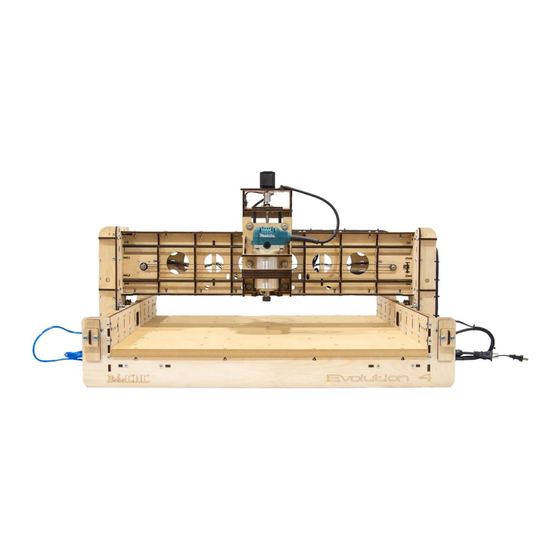
Page 129: Completed Views
Completed Views Front View Back View... - Page 130 X1 Side View X1 Home Switch...
- Page 131 X2 Side View X2 Home Switch...
- Page 132 Z Home Switch Y Home Switch...
-
Page 134: Tramming
The simplest method to do this is to use a square as shown. If the Spindle is not perpendicular, the Evolution Series CNC Routers can be trammed on the X axis by adjusting the four Eccentric... - Page 135 The Spindle (Router) can be trammed on the Y axis by placing shims behind the SG20U Bearing Fender Washer. Placing the shim on the top will tilt the axis clockwise. Placing the shim on the bottom will tilt the axis counterclockwise.
-
Page 136: Congratulations! You Just Completed The Assembly Of Your Evolution 4
Congratulations! You Just Completed the Assembly of Your Evolution 4. Please review our Software Setup Guide for Software installation and setup. -
Page 137: Appendix
Appendix Evolution 4 Firmware Values Value Description 10 (step pulse, usec) 25 (step idle delay, msec) 0 (step port invert mask:00000000) 0 (dir port invert mask:00000000) 0 (step enable invert, bool) 1 (limit pins invert, bool) 0 (probe pin invert, bool) 1 (status report mask:00000011) 0.01 (junction deviation, mm) 0.002 (arc tolerance, mm) -
Page 138: Evolution Washer Dimensions
$110 10000 (x max rate, mm/min) $111 10000 (y max rate, mm/min) $112 2000 (z max rate, mm/min) $120 500 (X-axis acceleration, mm/sec^2) $121 500 (Y-axis acceleration, mm/sec^2) $122 500 (Z-axis acceleration, mm/sec^2) $130 610 (X-axis maximum travel, millimeters) $131 610 (Y-axis maximum travel, millimeters) $132 85 (Z-axis maximum travel, millimeters) -
Page 139: Evolution 4 Spoilboard Drawing
Evolution 4 Spoilboard Drawing The recommended Spoilboard material is ¾” MDF. M4 x 16 mm Machines screws will work with a 10mm deep counter bore. Other holes shown are for threaded inserts and can be placed as desired.
Need help?
Do you have a question about the Evolution Series and is the answer not in the manual?
Questions and answers