BobsCNC Evolution 4 Assembly Instructions Manual
Extension kit
Hide thumbs
Also See for Evolution 4:
- Assembly manual (139 pages) ,
- Assembly instructions manual (52 pages)
Table of Contents
Advertisement
Quick Links
Advertisement
Table of Contents

Related Manuals for BobsCNC Evolution 4


Summary of Contents for BobsCNC Evolution 4
- Page 1 Evolution 4 Extension Kit Assembly Instructions Rev. 1.4...
-
Page 2: Table Of Contents
Contents Information/Warning Boxes ............................5 Safety Precautions and Warnings ..........................6 Getting Started ................................. 7 Required Tools: ................................7 Assembly Recommendations: ............................ 7 Removing Components: ............................... 9 Illustrated Step by Step Instructions ........................9 Step 1..................................9 Step 2..................................10 Step 3.................................. - Page 3 Step 7..................................21 Connecting the X Axis Extension ..........................22 Illustrated Step by Step Instructions ........................ 22 Step 1..................................22 Step 2..................................23 Step 3..................................24 Step 4..................................25 Step 5..................................26 Step 6..................................26 Step 7..................................27 Step 8..................................27 8a....................................
- Page 4 Step 2..................................35 Updating Firmware ..............................36 Evolution 4 Extension Firmware Value Change .................... 36 Appendix ($130=1283) .............................. 37 Evolution 4 Firmware Values ..........................37...
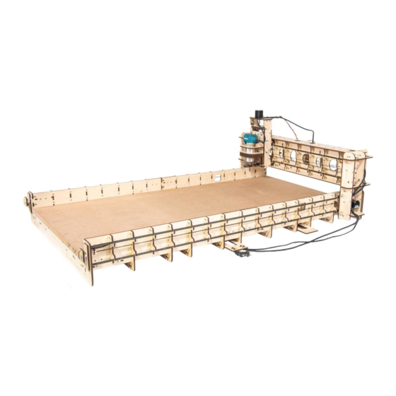
- Page 5 EVOLUTION 4 with Extension Specifications The Assembled Footprint: Length: 58.7" (1490 mm) Width: 39" (994 mm) Height: 20.9" (530 mm) Assembled Weight: 48 lbs. Cutting Area: 50.5" (1283 mm) 24" (610 mm) 3.3" (85 mm) Components needed to complete the kit: 1.
-
Page 6: Information/Warning Boxes
Safety is the First Priority. Always wear proper protective equipment and use "safety sense" when assembling and operating your Evolution 4 CNC Router. Information/Warning Boxes CAUTION Indicates a possible risk of injury that can result from failure to follow this... -
Page 7: Safety Precautions And Warnings
Safety Precautions and Warnings Evolution Series CNC Routers have a 110 v. power supply and use bits that spin at 28,000 rpm with cutting edges that are sharp and hazardous. The operator must understand the potential hazards and is responsible to take appropriate safety precautions before operating the Router. -
Page 8: Getting Started
Set of Metric Sockets and SAE Wrenches. Set of Metric and SAE Allen Wrenches. Assembly Recommendations: Use a large, flat, clean work surface for assembling your EVOLUTION 4. All Screws (unless noted) should be installed snug, then rotated 1-2 ½ turns. - Page 9 Try using strips of 1inch blue painters’ tape behind the T-Slots to help hold the Nuts in place during assembly. Lock Nuts are never used to secure components that have T-Slots. They are only used to mount components where the Nut is not held in a T-Slot.
-
Page 10: Removing Components
Removing Components: Illustrated Step by Step Instructions Before you can add the extension kit you will need to remove several components. Step 1 Remove and discard Spoilboard. -
Page 11: Step 2
Step 2 Remove and discard Belts by first loosening the Belt Tensioner. Be sure to keep the Belt Retainers. -
Page 12: Step 3
Step 3 Remove front Frame End Support and set aside for later assembly. Step 4 Remove both sides of the front Frame Corner Supports and set aside for later assembly. -
Page 13: Step 5
Step 5 Remove both sides of the Frame Corner Braces and set aside for later assembly. Step 6 Clip and remove the Zip Ties that secure the USB Cable and Power Cords to the Wire Harness Supports. -
Page 14: Step 7
Step 7 Slide Gantry Assembly off the Rails and carefully set it aside. Step 8 Remove the four X Rails and discard. The X frame I now ready once the extension is built. Set aside t X frame for later assembly... -
Page 15: Axis Extension Assembling
X Axis Extension Assembling Wood Components Part # Description Photo Rail Support Frame Mid Support Extension Frame Mid Support Extension Frame Side Support Wire Harness Support Coupling EX12 Plate... -
Page 16: Hardware
Hardware Part # Description Photo M4 x 16 Machine Screw M4 Nut M4 Locknut GT2 Belts Illustrated Step by Step Instructions Step 1 Align the slots in EX12 Coupling Plates to the tabs in the EX4 Extension Frame Mid Support at both ends and press in place. -
Page 17: Step 2
Step 2 While holding the Coupling Plates in place, position the Extension Mid Frame Support at the open end of the Evolution X Frame Assembly. Make sure the Coupling Plates are aligned to the outside of the Frame Side Support as shown. Align the slots in the Coupling Plates to the tabs in the Frame Side Support and secure each side with four M4 x 16 Screws and Lock Nuts. -
Page 18: Step 3
Step 3 Align the tabs of three X1 Rail Supports to slots of the EX5 Extension Frame Side Supports and secure each with three M4 16 Screws and Nuts. -
Page 19: Step 4
Step 4 Attach the Frame Corner Supports and secure with two M4 x 16 Screws and Nuts for each piece. -
Page 20: Step 5
Step 5 Attach the Frame Corner Braces and secure to the Extension Frame Side with two M4 x 16 Screws and Nuts for each Brace. -
Page 21: Step 6
Step 6 Align the tabs of the X4 Frame Mid Supports with the slots in the Extension Frame Side Supports and secure with two M4 x 16 Screws and Nuts on each side. Repeat for the remaining 3 of the Frame Mid Supports. -
Page 22: Step 7
Step 7 Align the tabs of the X7 Wire Harness Supports with the slots in the Extension Frame Side Supports and secure with one M4 x 16 Screw and Nut each side. -
Page 23: Connecting The X Axis Extension
Connecting the X Axis Extension Illustrated Step by Step Instructions Step 1 Attach the Extension Assembly to the Evolution X Frame. Make sure the Coupling Plates are oriented to the outside of the X Frame Extension Side Supports as shown. -
Page 24: Step 2
Step 2 While aligning the components, make sure the tabs of the Wire Harness fit into the adjoining slots of the X Frame Mid Support. Secure the Coupling Plate with four M4 x 16 Screws and Locking Nuts and the Wire Harness Support with one M4 x 16 Screw and Nut. Repeat for the other side. - Page 25 Step 3 The kit requires 4 each of 5/16” Stress Proof rods that will be cut to 56 7/8” in length (rods are not included). The rod ends should be filed or sanded to remove the burrs. Insert each of the 4 rails starting from one end while moving through each support.
-
Page 26: Step 4
Step 4 Carefully reinstall the Gantry Assembly. -
Page 27: Step 5
Step 5 Reinstall the Frame End Support and secure with twelve M4 x 16 Screws and Nuts. Step 6 Secure the USB Cable to the underside of the Wire Harness with Zip Ties as shown. -
Page 28: Step 3
Step 7 Secure the Power Cords to the underside of the Wire Harness with Zip Ties as shown. Step 8 Installing the longer X GT2 Belts. Cut two of the GT2 Belts to a length of 60 7/8 inches. Insert one end of the Belt into the X9 Short Belt Retainer. - Page 29 Next, thread the free end of the GT2 Belt through the Rail Stop (X3). NOTE: In the photo, the Rail Stop has been rotated so that the slot is oriented toward the bottom of the Rail Stop. Pull the belt through and insert the Short Belt Retainer through the Rail Stop as shown.
- Page 30 Note: Slide the Gantry Assembly in front of the square access hole. This opening provides the access you need to loop the Belt around the Idler and Flange Bearings. We suggest that you watch the short video demonstrating how to correctly route and install the Belts around the Flange and Idler Bearings.
- Page 31 Loop the Belt over the Belt Pulley so that the Belt teeth engage the teeth of Pulley. Finished Belt Routing viewed through the access port. Repeat for the other X Belt.
-
Page 32: Step 9
Step 9 Securing the X1 and X2 Belts Insert two M6 x 30 Machine Screws through the Belt Adjustment Plate (X11) and secure with a M6 Nut. Add one M6 Nut to each Machine Screw as shown. Insert the Long Belt Retainer (X10) through the Belt Adjusting Plate into the Rail Stop (X3) as shown. - Page 33 Insert the Belt Tightening Assembly into the upper slot of the X Assembly as shown. Insert the end of the Belt into the Belt Retainer. Be sure to seat the Belt completely in the Retainer as shown.
-
Page 34: Step 10
Step 10 Tighten the X1 and X2 Belts. Make sure the Nut closest to the Belt Adjusting Plate is tight. Using a 10mm wrench, hold the adjustment Nut and turn the machine screw to tighten the Belt. Be sure to adjust both Screws the same amount until the Belt is tight. -
Page 35: Adding A Spoilboard
Adding a Spoilboard Step 1 Cut two 17-inch and eight 28-inch pieces of 1 x 2 stock (not included). These will serve as battens that you can screw into to secure your spoilboard. Align the pieces so that their top edge is approx. -
Page 36: Step 2
Step 2 Cut a piece of ¾” MDF for the spoilboard, (not included) 28- 1/2” wide and 57- ½” long. Make sure the location of your battens is marked and easily visible. Attach the spoilboard to the battens. Countersink screws at least ¼”... -
Page 37: Updating Firmware
Updating Firmware Evolution 4 Extension Firmware Value Change Connect the CNC to the USB and connect to UGS Platform. Type in $130=1283 in the command textbox of the console window of UGS and press the enter key. This will change the soft limit for the X axis to the new value of 1283mm (50.5”) -
Page 38: Appendix ($130=1283)
Appendix ($130=1283) Evolution 4 Firmware Values Value Description (step pulse, usec) (step idle delay, msec) (step port invert mask:00000000) (dir port invert mask:00000000) (step enable invert, bool) (limit pins invert, bool) (probe pin invert, bool) (status report mask:00000011) 0.01 (junction deviation, mm) 0.002... - Page 39 $111 10000 (y max rate, mm/min) $112 2000 (z max rate, mm/min) $120 (X-axis acceleration, mm/sec^2) $121 (Y-axis acceleration, mm/sec^2) $122 (Z-axis acceleration, mm/sec^2) $130 1283 (X-axis maximum travel, millimeters) $131 (Y-axis maximum travel, millimeters) $132 (Z-axis maximum travel, millimeters)
Need help?
Do you have a question about the Evolution 4 and is the answer not in the manual?
Questions and answers