Table of Contents
Advertisement
Quick Links
Advertisement
Table of Contents

Related Manuals for Elecro Engineering H.R.UV-C


Summary of Contents for Elecro Engineering H.R.UV-C
- Page 1 H.R.UV-C Installation & Operating Manual HR-55 HRP-55 HR-110 HRP-110...
-
Page 2: Important Notes
Important Notes Congratulations on purchasing the H.R.UV-C pool sanitising system, the latest in UV technology, manufactured in England to the highest standards. To ensure your new product will give years of trouble free service please carefully read the following instructions. -
Page 3: Product Overview
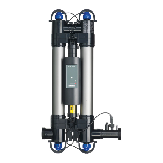
Product Overview The H.R.UV-C is available in 55W single tube and 110W double tube formats, supplied complete with flow switch and either an analogue lamp life indicator and reset switch, or digital lamp life countdown with intelligent dosing pump. 55W Single Tube Unit Note: Digital Model Shown Fig 1. - Page 4 110W Double Tube Unit Fig 2. Note: Digital Model Shown www.elecro.co.uk...
-
Page 5: Positioning The Unit
CAUTION: To prevent this unit falling into water, do not install above or alongside your pool. The H.R.UV-C unit is weatherproof but not waterproof; it must be installed in a dry weatherproof enclosure. The unit must be mounted on a flat vertical surface horizontally or vertically. - Page 6 Fig.4 Mounting the UV Unit The unit may be mounted on a wall or other suitable vertical surface that is structurally strong enough (for example: when full of water the unit is too heavy to mount onto a conventional wooden fence panel). The unit is supplied with a fixing kit.
- Page 7 55W Single Tube Unit Raw plug x5 Screw x4 Washer x4 Fig 5. www.elecro.co.uk...
- Page 8 110W Double Tube Unit Raw plug x5 Screw x5 Fig 6. Washer x5 www.elecro.co.uk...
- Page 9 Mounting Continued 110W Double Tube Unit Fig 7. Horizontal mounting Water must enter low and exit high Vertical mounting Factory Default Optional reverse flow explained on page 10 55W Single Tube Unit Vertical Factory Default mounting Optional reverse flow explained on page 10 Horizontal mounting Water must enter low and exit high...
-
Page 10: Connection To The Water Supply
Connection to the water supply The unit is supplied with unions to allow connection to 2" or 63-mm rigid pipe. Reducers are also supplied to allow connection to 50-mm or 1½" rigid pipe - see fig. 8. For connection to 63-mm or 2" diameter pipe Fig 8. -
Page 11: Flow Requirements
55W (single tube) = 12m3/hour (12,000 litres per hour) 110W (double tube) = 24m3/hour (24,000 litres per hour) Your H.R.UV-C is factory set to accept input water flow entering on the left and exiting on the right, this can be reversed by rotating the flow switch 180 degrees (i.e ½... - Page 12 At initial ‘Power On’ of the H.R.UV-C the LED indicator will light in Red colour for one second to indicate that the time setting is 9,000 hours, and immediately change colour to Green to indicate that the timer has started.
- Page 13 RESET SWITCH LAMP LIFE INDICATOR Fig 9. www.elecro.co.uk...
- Page 14 Lamp Life Indicator + Intelligent Dosing Pump (Digital) How to connect the suction tube to the dosing pump: This is how the completed assembly will look STEP ONE Components required: Foot Valve Strainer Tubing STEP TWO Unscrew securing cap anti-clockwise www.elecro.co.uk...
- Page 15 STEP THREE Thread tube through the securing cap (1) and component (2), then push the pipe onto component (3) STEP FOUR Once all components are looped through the tubing tighten securing cap Connection point STEP FIVE Lastly unscrew the retaining gland and insert tube over Retaining the connection point.
- Page 16 DIGITAL DISPLAY LED INDICATOR Fig 11. BUTTONS Fig 12. The language menu is displayed on each power up of the unit. The factory default setting for the language is English. To change to another language, press the buttons until the de- sired language appears, press OK to select and save.
- Page 17 The digital controller has four programmable functions: • UV Lamp Life • Shock Dose • Dose Chemical • Set Time Fig 13. To select a mode press the buttons until the desired mode is displayed then press the OK button to select that mode. Operation: When the unit is powered on the UV lamp is switched on, the UV lamp will switch off under the following conditions ie:...
- Page 18 When the UV lamp(s) are replaced the lamp life timer must be reset to 9,000 hours. In the UV lamp life mode select ‘Reset UV Lamp’ by pressing and releas- ing the O.K. button, then immediately press and hold the O.K. button until the display shows ‘SAVED’...
- Page 19 NOTE: If the dosing volume is set to 0.0 (ml) the peristaltic pump will remain off. NOTE: In the event of power loss: the programmed settings (dosing volume and dosing time) will remain stored. If the power to the controller is switched off for longer than 3-Hours the current time will need to be re-programmed, this is indicated to the operator by the clock flashing.
- Page 20 NOTE: When dosing with liquid chlorine the daily dosage amount should be halved to enable half the dose to be delivered in the morning (CL 1 DOSE) and half the dose to be delivered in the afternoon (CL 2 DOSE). NOTE: The controller does not monitor the free chlorine level.
- Page 21 NOTE: In the event of power loss: the programmed settings (dosing volume and dosing time) will remain stored. If the power to the controller is switched off for longer than 3-Hours the current time will need to be re-programmed, this is indicated to the operator by the clock flashing. Set Current Time: To complete the set up you need to programme the current time: Use the buttons until ‘SET TIME’...
- Page 22 Intelligent Dosing Pump Routine Maintenance We recommend that the dosing tube is changed every 12 months in order to prevent any wear and tear and keep performance to an optimum. The following steps will guide you how to replace the dosing tube: STEP ONE Unscrew the two screws securing the plastic cover and remove.
- Page 23 STEP FOUR Take the replacement tube and re-attach connection points. Loop secur- ing ties in place in order to seal to the connection points. Once securely in place cut the excess tie and dispose of. STEP FIVE Place dosing tube into position on the left-hand side.
-
Page 24: Frost Protection
Frost Protection It is essential that the unit is protected from frost during the winter months, or disconnected from the water and electricity supply and stored inside a dry weather proof enclosure. Lamp Replacement & Quartz Glass Cleaning (all models) Isolate from the electrical and water supplies before carrying out any maintenance. - Page 25 Wipe a little silicone grease or Vaseline (not silicone sealant) onto these threads. As these threads are only serviced periodically, this lubrication will help to prevent them binding together. Then refit and firmly hand tighten the compression fittings. Refit or replace the UV lamp(s) with a new one. Relocate the lamp holders and blue lamp holder shrouds ensuring that you match the correctly numbered lamp holder.
-
Page 26: Rohs Compliance Statement
Guarantee Your H.R.UV-C pool sanitiser is guaranteed for 2 years from the date of purchase against faulty workmanship and materials. The manufacturer will replace or repair, at it’s discretion, any faulty units or components returned to the company for inspection. - Page 27 Calculating Pool Volumes The following pages will show you how to calculate the volume of your pool. NB For pools with different depths: D1 + D2 = Average Depth If your pool has a sloping bottom, then take the deepest measurement (D2) and the shallowest (D1).
- Page 28 Ellipses Depth (D) Volume = π (3.142) x A x B x Average Depth Irregular Shapes For irregular shapes, calculating the area is less accurate. You will need to draw up the pool accurately to scale on graph paper using a square on the paper to represent a metre (or foot) square of pool.
- Page 29 Useful Conversions Cubic Metres to Litres = Multiply by 1000 Cubic Feet to Cubic Metres = Multiply by 0.0283168 UK Gallons to Litres = Multiply by 4.54609 Litres to Cubic Metres = Multiply by 0.001 Cubic Metres to UK Gallons = Multiply by 219.969 www.elecro.co.uk...
- Page 32 11 Gunnels Wood Park Stevenage Hertfordshire SG1 2BH United Kingdom | f: | e: +44 (0) 1438 749 474 +44 (0) 1438 361 329 sales@elecro.co.uk www.elecro.co.uk © Copyright 2017...
Need help?
Do you have a question about the H.R.UV-C and is the answer not in the manual?
Questions and answers