Table of Contents
Advertisement
Quick Links
Advertisement
Table of Contents

Related Manuals for Elecro Engineering HR-55


Summary of Contents for Elecro Engineering HR-55
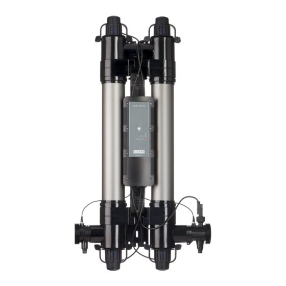
- Page 1 H.R.UV-C CLASSIC Installation & Operating Manual HR-55 HR-110 ENGLISH...
-
Page 2: Table Of Contents
CONTENTS IMPORTANT SAFETY INSTRUCTIONS ................... 3 PRODUCT OVERVIEW ........................3 GENERAL INSTALLATION INSTRUCTION ..................4 3.1 Mounting instructions ........................4 3.2 Pipe work ............................5 3.3 Flow direction ..........................7 3.4 Connection ............................. 8 3.6 Electrical connection ........................9 OPERATING INSTRUCTIONS ......................9 4.1 Flow requirements .......................... -
Page 3: Important Safety Instructions
Introduction Thank you for purchasing the H.R. UV-C pool sanitising system, manufactured to the highest standards in England. To ensure years of trouble-free service, please read and follow these instructions for proper installation, maintenance and use. Incorrect installation will affect your warranty. Please retain this manual for future reference. -
Page 4: General Installation Instruction
Dimensions: 3. GENERAL INSTALLATION INSTRUCTION 3.1 Mounting instructions The H.R.UV-C should be either installed horizontally or vertically allowing enough space for the pipe connections, wiring and maintenance of lamps/quartz sleeve. It should be firmly secured, using the fixing kit provided, to a solid wall. NOTE: When mounting the UV, it is essential to leave a clearance space of at least 1 metre from one side of the unit to allow access to replace the lamp(s) and/or quartz... -
Page 5: Pipe Work
See Fig. 3 for mounting instructions when securing to the wall. Fig. 3 3.2 Pipe work The H.R.UV-C should be placed downstream (after) of any pumps, filters and heating devices but upstream (before) of any chemical dosing or similar water treatment (see Figs.4 and 5). - Page 6 Fig. 4 Fig. 5...
-
Page 7: Flow Direction
3.3 Flow direction Fig. 6 H.R.UV-C is factory set to accept input water flow entering on the left and exiting on the right, this can be reversed by rotating the flow switch 180 degrees (i.e. ½ turn - see Fig. 6). -
Page 8: Connection
WARNING: The flow switch paddle can be damaged when reversing the flow direction if it is lifted by more than 5mm from its housing and turned with force. If the flow switch has been rotated it is important to ensure that it is finally locked in the correct orientation perpendicular (at right angles) to the flow of water. -
Page 9: Electrical Connection
3.6 Electrical connection • This device must be installed by a qualified Electrician following the WARNINGS: instructions provided in this manual. The manufacturer will not be liable for any issues caused by poor or improper installation. • Any alterations made to the unit (unless stated) will affect the warranty. This also applies if components are changed for non-standard components acquired anywhere other than direct from the manufacturer. -
Page 10: Water Quality
4.3 Water quality The water quality MUST be within the following limits: • PH: 6.8 – 8.0 • Total Alkalinity (TA): 80 – 140 ppm (parts per million) • Chloride Content MAX: 150 mg/litre • Free Chlorine: 2.0 mg/litre • Total Bromine: Max 4.5 mg/litre •... -
Page 11: Lamp Replacement And Quartz Sleeve Cleaning
5.2 Lamp replacement and quartz sleeve cleaning Removing the lamp and quartz sleeve Unclamping the clip from body 1. Pull the clip in shown direction to Unscrew all the highlighted fasteners unlock from body 2. Pull the second side after unlocking the side Remove Lamp holder Clip from Hard Unmount the Hard cap from Blue lamp Holder... - Page 12 Slide the O-ring off the quartz sleeve Unscrew the blue quartz sleeve locking nut anticlockwise. Both ends must be unscrewed before the quartz sleeve can be removed The quartz sleeve can now be removed. NOTE: To avoid bending the pins of the lamp during the reassembly pull the plastic fitting out of the shroud. Connect it to the lamp and push the shroud back in to place.
-
Page 13: Disposal Of Electrical/Electronic Equipment
If you live in a hard water area there may be some limescale on the quartz sleeve. This can be easily removed by soaking the sleeve in a proprietary kettle descaling solution (follow the manufacturer’s instructions). NOTE: Failure to remove the limescale will limit the effectiveness of the UV lamp(s). Assembly process •... -
Page 14: Warranty
7. WARRANTY This product is guaranteed from the date of purchase against faulty workmanship and materials for: – two years within Europe – one year outside Europe • The manufacturer will replace or repair, at its discretion, any faulty units or components returned to the Company for inspection. - Page 15 Elecro Engineering Ltd Repairs Department Unit 11 Gunnels Wood Park Gunnels Wood Road Stevenage Hertfordshire SG1 2BH United Kingdom __________________________________________________________________________________ Customer Information: (ATTACH TO HEATER) ………………………………………………………………………………. Company Name: ………………………………………………………………………………. Contact Name: Daytime Telephone Number: ………………………………………………………………………………. ……………………………………………………………………………….. Email Address: ……………………………………………………………………………….. ………………………………………………………………………………..
- Page 16 Unit 11, Gunnels Wood Park, Stevenage, Herts SG1 2BH Sales@elecro.co.uk www.elecro.co.uk +44 (0) 1438 749474 © Copyright MANE61-EN-H.R.UV-C CLASSIC Manual V1-31.08.2021-Elecro...
Need help?
Do you have a question about the HR-55 and is the answer not in the manual?
Questions and answers