Advertisement
Quick Links
—
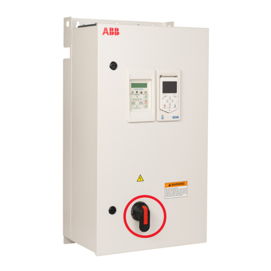
ACH580-01 BxR, UL Type 1/12
Frame R1/R2
Base drive replacement instructions
Purpose or Scope
The following are the instructions for replacing an ACH580-01 UL Type 1 and 12 (Frames
R1 & R2) drive in BxR enclosures.
Equipment required*:
– Replacement drive (see note below)
– T20 bit
– T30 bit
– PZ2 bit
– PZ3 bit
– Torque wrench
– Zip ties
Basic overview of steps
– Back-up drive parameters (if you can)
– Remove power and verify after 5 minutes
– Open enclosure
– Disconnect all wiring
– Remove flange plate
– Remove drive
– Prepare replacement drive
– Remove conduit assembly
– Install in reverse order
– Check connections
– Power drive
– Reprogram and test
Notes and cautions
CAUTION! Review complete safety and electrical considerations prior
to replacing the drive. See ACH580 IOM (3AXD50000049127).
CAUTION! Two people are recommended for this job. The drive is
heavy and can fall, causing property damage and injury.
NOTE: UL Type 12 drives require a UL Type 12 replacement drive,
UL Type 1 drives are not allowed as substitutes for UL Type 12.
* Not all of these tools are needed for each frame size.
Advertisement

Related Manuals for ABB ACH580-01 BxR Frame R1


Summary of Contents for ABB ACH580-01 BxR Frame R1
- Page 1 — ACH580-01 BxR, UL Type 1/12 Frame R1/R2 Base drive replacement instructions Purpose or Scope The following are the instructions for replacing an ACH580-01 UL Type 1 and 12 (Frames R1 & R2) drive in BxR enclosures. Equipment required*: – Replacement drive (see note below) –...
- Page 2 REPLACEMENT INSTRUCTIONS | ACH580-01 BXR UL TYPE 1 & 12, R1/R2 Step Instruction Diagram NOTE: If needed, back-up parameters prior to disconnecting power. Turn off source power and wait 5 minutes for the DC bus capacitors to discharge. Turn handle to the off position. Rotate latches clockwise and open the enclosure door.
-
Page 3: Step Instruction
REPLACEMENT INSTRUCTIONS | ACH580-01 BXR UL TYPE 1 & 12, R1/R2 Step Instruction Diagram Cut zip tie and remove the CDPI from drive. Set aside. Cut zip tie and disconnect the RS485 cable from the drive by pulling out the terminal block. NOTE: Remove any additional drive I/O wiring. - Page 4 REPLACEMENT INSTRUCTIONS | ACH580-01 BXR UL TYPE 1 & 12, R1/R2 Step Instruction Diagram Using a T30 bit, loosen the four (4) M6 screws securing the drive, four (4) turns of the screw. NOTE: Do not remove the screw completely. Only loosen enough to be able to lift the drive off the screws.
- Page 5 REPLACEMENT INSTRUCTIONS | ACH580-01 BXR UL TYPE 1 & 12, R1/R2 Step Instruction Diagram Using a T20 bit, loosen and remove two (2) M4x8 screws. Remove conduit assembly. Recycle the conduit assembly and hardware. CAUTION! Use two people to install the drive. Slide the drive mounting holes over the four (4) screws and slide drive in place.
- Page 6 REPLACEMENT INSTRUCTIONS | ACH580-01 BXR UL TYPE 1 & 12, R1/R2 Step Instruction Diagram Place collar around drive. Using a T20 bit, secure the drive using the six (6) M4x20 screws that were removed earlier. Using a T20 bit, torque to 14 in-lb (1.5 Nm). Secure the ground wire to the drive.
- Page 7 REPLACEMENT INSTRUCTIONS | ACH580-01 BXR UL TYPE 1 & 12, R1/R2 Step Instruction Diagram Connect the input wires (from fuse block) to the Input Terminals of the drive. Yellow U1 to L1 Black V1 to L2 Red W1 to L3 R1 Frame: Using PZ2 bit, torque terminals to 5 in-lb (0.5 Nm).
- Page 8 REPLACEMENT INSTRUCTIONS | ACH580-01 BXR UL TYPE 1 & 12, R1/R2 Step Instruction Diagram Power and reprogram the drive. Test and verify drive operation and motor direction. Back-up and save parameters to the keypad prior to putting the drive back into service.