Table of Contents
Advertisement
Quick Links
Advertisement
Table of Contents

Related Manuals for wtw EcoLine pH 170


Summary of Contents for wtw EcoLine pH 170
- Page 2 To ascertin the warranty liability, return the meter and proof of purchase together with the date of purchase freight paid or prepaid. Copyright Weilheim 2006, WTW GmbH Reprinting – even in the form of excerpts – is only allowed with the explicit written authorization of WTW GmbH, Weilheim.
-
Page 3: Safety Instructions
"Technical data" in this operating manual. − Opening of the instrument as well as adjustment and maintenance or repair work must only be performed by personnel authorized by WTW. Depending on the severity, contravention can lead to loss of warranty. -
Page 4: Table Of Contents
pH 170/ Contents pH 296 Safety instructions ....................93 Description ......................97 Front views ......................97 Control panel ......................98 Display ........................ 98 Display messages ....................99 Keyboard ......................101 Operating instructions ..................101 Operating levels ....................102 Installation ......................104 General instructions .................... - Page 5 pH 170/ Contents pH 296 Configuration......................120 Factory settings ..................... 120 Calling up the configuration level ................121 Overview table of the submenus ..............122 Selecting the measuring mode ................122 Selecting the calibrating procedure ............... 123 Selecting the temperature compensation .............. 124 Selecting the sensor ....................
- Page 6 pH 170/ Contents pH 296 Viewing mode ...................... 155 Displaying the parameterization and configuration data ........155 Displaying the calibration data and software version ........155 Measuring mode ....................156 Calibration ......................157 Calling up the calibrating mode ................157 AutoCal TEC and AutoCal TEC calibrating procedures with buffer output .....157 % @@ Calibration error,...
-
Page 7: Description
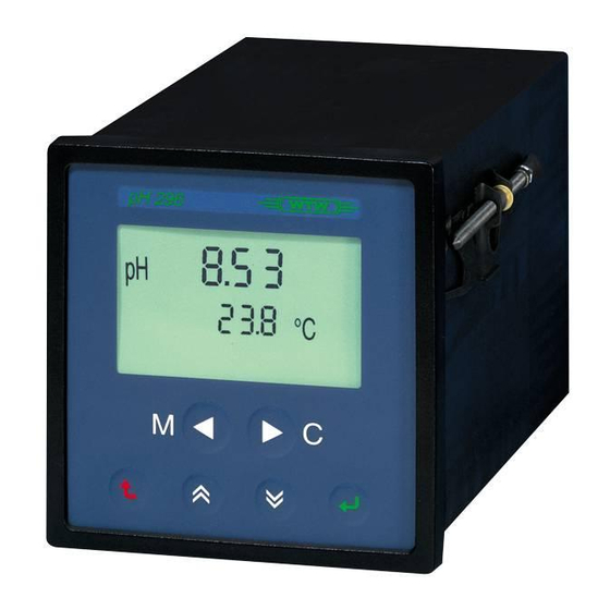
pH 170/ Description pH 296 Front views pH 170 pH 296 pH 296... -
Page 8: Control Panel
pH 170/ Description pH 296 Control panel Display pH measuring mode Calibration: AutoRead “Active “ Relay 1 is active (flashes if check Slope/ Measuring chain (#, ( ) is active) Alphanumeric display: Calibration procedure with technical measured value, slope, asymmetry, buffers selected user interface Dimensions:... -
Page 9: Display Messages
pH 170/ Description pH 296 Display messages Note: The first letter of a display message is used for allocation. Configuration displays have a “C” as the first letter and a "P" identifies displays of the parameterization. Configuration: nfiguration onfiguration nction onfiguration ibration onfiguration... - Page 10 pH 170/ Description pH 296 General: ® SensoLyt ® SensoLyt >B9 er Probes 1000 unction ower upply eeze ontact pper imit ower imit roportional mpulse roportional requency lose (@> portional band ntervall requency "* teresis elay tmodus *< avemodus Checking Mode: >5 enumber BAB@6...
-
Page 11: Keyboard
pH 170/ Description pH 296 Keyboard • Operating keys to switch between Measurement (M) and Calibration (C) • Function keys to switch between the operating levels and changing of setting values in configuration and parameterization. ESCAPE to leave a menu to increase a value or to scroll upwards in scrolling mode DOWN... -
Page 12: Operating Levels
pH 170/ Description pH 296 Operating levels The instrument functions are incorporated in three levels consecutively structured to ensure a clear and transparent structure. This structure ensures that the user is provided with an instrument that, although it has universal options, can still be set so that unauthorized actions do not interfere with the reliable measuring mode. - Page 13 pH 170/ Description pH 296 Note: After a power fail, the instrument returns to the previous operating mode. All settings are preserved.
- Page 14 II, i.e. no protective earth conductor is required. Do not feed the protective earth conductor into the instrument or connect it to an instrument terminal or to a supply line! Only authorized WTW technicians are allowed to change the instrument fuse.
- Page 15 pH 170/ Installation pH 296 "SENS-CHECK" connection The "SENS-CHECK" relay is designed as a closing contact that is electrically isolated from the instrument; it is then always active (= closed) if a sensor error occurs. This message is also output on the display. Sensor errors in the switching station are displayed using the relay.
- Page 16 pH 170/ Installation pH 296 RS 485 digital interface (RS option) The RS 485 interface operates with differential levels that are not susceptible to interference. In this way, cable lengths of up to 1 km long can be implemented. The instruments are connected via a 2-wire line.
- Page 17 Installation pH 170 Installation instructions for the pH 170 A sensor can be connected to the measuring transmitter via the sensor input socket or the terminal strip. Set the connection location with the dip switch on the circuit board of the pH 170: Connection of the sensor Dip switch Terminal strip...
- Page 18 Installation pH 170 Terminal Terminal assignment (RS 485 option) REC 1 + (RS 485 option) REC 1 – GND (RS 485 option) REC 2 + Sens-Check REC 2 – Sens-Check a (sensor) K1 (R option) b (sensor) K1 (R option) c (sensor) K2 (R option) d (sensor)
- Page 19 Installation pH 170 Connecting the SensoLyt 650 The Dip switch must be in the “ON“ position. Dip switch 11 10 13 12 Netz Option Option Mains Unused wires must not jut into the housing. Otherwise, malfunctions can occur. This especially applies to the ground wire of the mains cable.
- Page 20 Installation pH 170 Terminal Terminal assignment A (RS 485 option) REC 1 + B (RS 485 option) REC 1 – GND (RS 485 option) REC 2 + Sens-Check REC 2 – Sens-Check – K1 (R option) – K1 (R option) –...
- Page 21 Installation pH 170 Connecting the SensoLyt 690 or SensoLyt 700 The Dip switch must be in the “OFF“ position. Dip switch...
- Page 22 Installation pH 170 Connecting a high-resistance probe with external temperature probe (Example: NTC / PT 100 / PT 1000) The Dip switch must be in the “ON“ position. 13 12 Sensor/Probe Rec2 Rec1 Netz Option Option Mains AS 9-HI For three-wire conductors onlyr Optional temperature sensor, e.
- Page 23 Installation pH 170 ® Connecting a InPro 4250 (high-resistance) The Dip switch must be in the “ON“ position. Dip switch 13 12 Netz Option Option Mains 10 9 8 VP6-ST Terminal Terminal assignment A (RS 485) REC 1 + B (RS 485) REC 1 –...
- Page 24 Installation pH 296 Installation instructions for the pH 296 Terminal assignment RS 485 Recorder digital output interface Sens-Check Contact- Relay 1 outputs Sensor Relay 2 Power supply AC DC Unused wires must not jut into the housing. Otherwise, malfunctions can occur. This especially applies to the ground wire of the mains cable. Cut off unused wires in the housing as close to the armored thread joint as possible.
- Page 25 Installation pH 296 Connecting the SensoLyt 650 Unused wires must not jut into the housing. Otherwise, malfunctions can occur. This especially applies to the ground wire of the mains cable. Cut off unused wires in the housing as close to the armored thread joint as possible.
- Page 26 Installation pH 296 Connecting the SensoLyt 690 or SensoLyt 700 ADA / AMPH Unused wires must not jut into the housing. Otherwise, malfunctions can occur. This especially applies to the ground wire of the mains cable. Cut off unused wires in the housing as close to the armored thread joint as possible.
- Page 27 Installation pH 296 Terminal Terminal assignment A (RS 485) REC 1 + B (RS 485) REC 1 – GND (RS 485) REC 2 + Sens-Check REC 2 – Sens-Check pink Relay 1 white Relay 1 blue Relay 2 green Relay 2 –...
- Page 28 Installation pH 296 Connecting a high-resistance probe with external temperature probe (Example: NTC / PT 100 / PT 1000) For three-wire conductors only Optional temperature sensor, e. g. PT 100 NTC (two-wire conductor) PT 1000 PT 100 (three-wire conductor) PT 1000 (three-wire conductor) Shield For example:...
- Page 29 Installation pH 296 ® Connecting a InPro 4250 (high-resistance) VP6-ST white gray green copper and yellow/green transparent blue = unused Terminal Terminal assignment A (RS 485) REC 1 + B (RS 485) REC 1 – GND (RS 485) REC 2 + Sens-Check REC 2 –...
- Page 30 pH 170/ Configuration pH 296 The configuration defines the operating mode of the instrument. To do this, the configuration level is split into submenus (see the flow diagram). The submenus only offer those setting options that have not yet been established on the basis of the previous configuration of the program.
- Page 31 pH 170/ Configuration pH 296 Calling up the configuration level − Press the DOWN key. − Press the ENTER key. The display shows the following: The first numeral flashes. No code number is set in the delivery state. To access the configuration level −...
- Page 32 pH 170/ Configuration pH 296 Overview table of the submenus Display Description Option Basic Relay T option instrument Select the measuring mode Select the calibrating procedure Select the temperature compensation & Select the sensor type Select recorder 1 Select recorder 2 Assignment of the pilot relay Operating mode of the pilot relay + Menu appears in the corresponding model of the instrument.
- Page 33 pH 170/ Configuration pH 296 Selecting the calibrating procedure The instrument can perform three calibration procedures (see also the section, Calibration): • Auto Cal TEC • Auto Cal TEC • − Use the UP / DOWN keys to select a calibration procedure. −...
- Page 34 pH 170/ Configuration pH 296 Selecting the temperature compensation In the submenu, the following setting options can be selected: Auto TP (automatic temperature compensation) • • TP (manual temperature compensation) − Select a compensation procedure by pressing the UP / DOWN keys. −...
- Page 35 pH 170/ Configuration pH 296 Selecting the sensor The following setting options can be selected: Display Sensor SensoLyt ® 690 SensoLyt ® 700 >B9 Other sensors: &B4 external sensor (e.g. SensoLyt ® 650) with NTC (e.g. temperature sensors TFK 150,TFK 325) external sensor with temperature sensor Pt 100 external sensor with temperature sensor Pt 1000 −...
- Page 36 pH 170/ Configuration pH 296 Selecting the REC 1 recorder output The display shows: If the recorder range is exceeded (OFL), the recorder outputs issue a constant signal of 20.5 mA. A return to the preset recorder range is performed automatically after eliminating the exceeding of the recorder range.
- Page 37 pH 170/ Configuration pH 296 C C C C Setting for = pH: − Press the ENTER key when the following display appears: − Press the UP / DOWN keys to change the upper value. − Press ENTER to confirm the input. The preset lower value appears: −...
- Page 38 pH 170/ Configuration pH 296 Selecting the REC 2 recorder output The display shows: If the recorder range is exceeded (OFL), the recorder outputs issue a constant signal of 20.5 mA. A return to the preset recorder range is performed automatically after eliminating the exceeding of the recorder range.
- Page 39 pH 170/ Configuration pH 296 Setting: − Press the ENTER key when the following display appears: − Press the UP / DOWN keys to change the upper value. − Press ENTER to confirm the input. The lower set value appears: −...
- Page 40 pH 170/ Configuration pH 296 Relay 1 / Relay 2 (R option) The display shows: Selecting the relay functions A function can be assigned to each relay: Function Description = (no function) Relay without any function (* (power supply) Contact is closed when power is applied and opens if there is a power fail @ (freeze) Is active if the measured value is frozen - e.g.
- Page 41 pH 170/ Configuration pH 296 Limit indicator (UL.LL) The following functions can be selected: pper imit ower imit Function Description UL pH UL mV upper limit – main parameter LL pH LL mV lower limit – main parameter UL °C UL °C upper limit –...
- Page 42 pH 170/ Configuration pH 296 Pulse regulator (PI) In impulse regulation, the output relay - within a preselected proportional band - is clocked and the switch contact is Relay closed for a longer or shorter time according to the deviation from the limit. •...
- Page 43 pH 170/ Configuration pH 296 Example: Measured value Rel 2 pH10 ;S 8/ ;S // Rel 1 rel. switching duration 90 % 10 % 10 % The following default limits are given: Rel1: LL = pH 6 Xp (LL) = 3 pH Rel2: UL = pH 8 Xp (UL) = 2 pH pH value = 6 to 8...
- Page 44 pH 170/ Configuration pH 296 Frequency regulator (PF) In frequency regulation - within a preselected proportional band - the output relay is clocked where the clock frequency is higher or lower Relay depending on the deviation from the limit. • In larger deviations of the measured value from the limit, the switching rate is higher.
- Page 45 pH 170/ Configuration pH 296 Example: Measured value Rel 2 pH10 ;S 8/ ;S // Rel 1 t [pulses./min.] The following default limits are given: Rel1: LL = pH 6 Xp (LL) = 3 pH tF = 70 Imp./Min. Rel2: UL = pH 8 Xp (UL) = 2 pH tF = 50 Imp./Min.
- Page 46 pH 170/ Configuration pH 296 Proportional band, Xp The proportional band Xp lies above or below the limiting value. When entering a PL UL (Upper Limit) limiting value, Xp begins above the respective limit whereas , when entering a PL LL (Lower Limit) limiting value, it begins below the respective limit.
- Page 47 pH 170/ Configuration pH 296 Setting procedure for pulse or frequency regulation Example − Press the UP / DOWN keys to select the relay function, e.g. for Relay 1. − Press ENTER to confirm the selection. REL1 − Use UP / DOWN to select between (Upper (Lower Limit) to set up the Limit) and...
- Page 48 pH 170/ Parameterization pH 296 The parameterization creates the numeric values of the functions for which the instrument is configured. Factory settings Adjustable function Setting Menu item Recorder output 1: Current range 4 to 20 mA Attenuation 20 mA/s Recorder output 2: Current range 4 to 20 mA Attenuation...
- Page 49 pH 170/ Parameterization pH 296 Calling up the parameterization level Calling up the parameterization level from the measuring mode − Press the DOWN key. − Press the ENTER key. The first numeral flashes. No code number is set in the delivery state. To access the configuration level −...
- Page 50 pH 170/ Parameterization pH 296 Overview table of the submenus Display Description Option Basic Relay RS-485 instrument Recorder output 1 Recorder output 2 Limiting value indicator RS 485 interface Manual temperature setting Set up the code number Temperature compensation Timer for external probe cleaning unit + Menu appears in the corresponding model of the instrument.
- Page 51 pH 170/ Parameterization pH 296 REC 1 and REC 2 recorder outputs (REC 2 only in T option) This submenu enables the setting of: • Current range − 0 to 20 mA − 4 to 20 mA • Attenuation [dI/dt] (dI = current change; dt = time change) 0.1 mA/s −...
- Page 52 pH 170/ Parameterization pH 296 Relay 1 / Relay 2 (R option) Limit indicator (UL.LL) submenu enables the allocation of the following values for the relay occupied by a limit function (UL.LL) in the configuration level: 1. Limiting value L (Limit) 2.
- Page 53 pH 170/ Parameterization pH 296 Setting the parameters for limit indicators Example: Set up the upper limit for “pH“ on relay 1. − Press the ENTER key to enter the submenu. − Press the ENTER key again to set this limiting value.
- Page 54 pH 170/ Parameterization pH 296 − Use the UP / DOWN keys to set the seconds (right-hand flashing digits) of the time delay. − Press the ENTER key to confirm the input. − Set the minutes (two numerals on the left) in the same way.
- Page 55 pH 170/ Parameterization pH 296 Pulse regulator / Frequency regulator submenu enables the allocation of the following values to the relay occupied with a control function (PI / PF) in the configuration level: 1. Limiting value L (Limit) 2. Proportional band 3.
- Page 56 pH 170/ Parameterization pH 296 Parameters for the pulse regulator / frequency regulator − Press the ENTER key to enter the submenu: − Press the ENTER key again to set this limiting value. The first/second/third or fourth numeral is flashing. −...
- Page 57 pH 170/ Parameterization pH 296 Setting the pulse regulator: submenu: − Use the UP / DOWN keys to set the time interval to between 5 and 100 sec. − Press the ENTER key to confirm the input. Setting the frequency regulator: submenu: −...
- Page 58 pH 170/ Parameterization pH 296 Example 1: Rel 1 was configured as a PI controller with the function of LL. A value of LL = pH 5.0 results in the possible proportional band of 0.1 pH to 5.00 pH. In a proportional band of 1.0 pH, the PI controller controls a range of pH 4.0 to pH 5.0 in proportion to the measured value.
- Page 59 pH 170/ Parameterization pH 296 RS 485 interface (RS option) Call up the (# submenu using ENTER: • The parameterization of the RS 485 interface is described in a separate manual that is included within the scope of delivery of instruments with a RS 485 interface (RS instrument version).
- Page 60 pH 170/ Parameterization pH 296 Redox shift This submenu enables the Redox potential to be shifted by ± 300 mV. The menu is only provided when the instrument is in the Redox measuring mode. If a correction of the measured value is undertaken, the correction value appears in the display (normal measuring mode).
- Page 61 pH 170/ Parameterization pH 296 Temperature input in manual temperature compensation The following submenu appears only in the manual temperature compensation in the pH measuring mode: − Call up the submenu using the ENTER key when the first numeral flashes. −...
- Page 62 pH 170/ Parameterization pH 296 Temperature compensation The (B submenu enables compensation of the temperature measuring sensor tolerances in the test probe (shifting of the zero point by a maximum of 0.5 °C) and appears only if, in the configuration of , the automatic temperature compensation was set.
- Page 63 pH 170/ Parameterization pH 296 Timer for an external probe cleaning unit (CS) The (% submenu allows for the allocation of the intervals for relays, which are configured in the configuration level to work as control relay for an external probe cleaning unit (CS).
- Page 64 pH 170/ Parameterization pH 296 Setting the intervals − Press the ENTER key. The menu to input the cleaning interval appears with the B@ display and the current value in the lower display line. − The first digit flashes. − Using the UP / DOWN keys set the flashing digit.
- Page 65 pH 170/ Viewing Mode pH 296 Displaying the parameterization and configuration data In the viewing mode, settings can be queried without having to input a code. However, the settings cannot be modified. To leave the measuring mode and go into the viewing mode, perform the following steps: −...
- Page 66 pH 170/ Measuring Mode pH 296 The pH 170 and pH 296 instruments are automatically located in the measuring mode following the first commissioning. Otherwise, the measuring mode - except in compelled guidance - can be called up from any operating level by pressing the M key (see also section, Operating instructions).
- Page 67 The calibration of the pH measuring is made according to the selected calibrating procedure. The following calibrating procedures are available: • Auto Cal TEC: Automatic calibration using the WTW technical buffer solutions for pH 2.00, 4.01, 7.00 or 10.00. • Auto Cal TEC with additional buffer output on the REC 1 output •...
- Page 68 pH 170/ Measuring Mode pH 296 Note: The calibration can be terminated by pressing the ESCAPE key. − Rinse the measuring chain and immerse it in the 1st buffer solution. − Use the ENTER key to start the calibration. The measurement runs until a stable measuring value is reached (AR flashes / display in mV).
- Page 69 pH 170/ Calibration pH 296 In "AutoCal TEC" with buffer output, the buffer values are output via relay 1 and recorder 1 (see AutoCal TEC with buffer output) % @@ Calibration error, % @@ error message appears if • no stable measured value was reached or •...
- Page 70 pH 170/ Calibration pH 296 AutoCal TEC with buffer value AutoCal 2 Techn. Techn. buffer 1 buffer 2 REL 1 Display Display buffer 1 buffer 2 REC 1 current meas. value REL 1 pulled up REL 1 pulled up only if REC 1 frozen REC 1 frozen calibration o.k.
- Page 71 pH 170/ Calibration pH 296 Calibration using any buffer solutions: "ConCal" Calibrating process: − Use the C (calibration) key to select the Calibration operating mode. The recorder outputs are frozen on the current value, the switching relays keep the current operating condition. The following display appears: Note: In manual temperature compensation, set the temperature of the buffer solution using the...
- Page 72 pH 170/ Calibration pH 296 Setting up the offset voltage ("Asymmetry" ASY) − Use the UP / DOWN keys to set the pH value of the first buffer solution according to the temperature. Note: ƒ& In manual temperature compensation, the buffer &DO temperature set up, otherwise the current buffer temperature, is displayed.
- Page 73 pH 170/ Calibration pH 296 Setting up the measuring chain slope − Use the UP / DOWN keys to set the pH value of the second buffer solution 2 according to the temperature. Note: °C In manual temperature compensation, the buffer temperature set up, otherwise the current buffer temperature, is displayed.
- Page 74 pH 170/ Calibration pH 296 Calibrating errors If the calibration routine is left after an invalid calibration, an error is output. Instead of the measured value, three lines appear on the display. The last measured value remains frozen. − Press ENTER: The cause of the error is displayed.
- Page 75 pH 170/ Checking Mode pH 296 The checking mode may only be used by trained specialist personal as special knowledge is required. The interfaces of the pH 170 or pH 296 and connected peripheral devices (e.g. recorder, PLC, PC, printer) can be checked in the checking mode. Furthermore, the user can display the code number.
- Page 76 pH 170/ Checking Mode pH 296 Recorder output 1 B*B @ A current of 0.1 mA is set in the submenu after pressing the ENTER key: − Press C to set the current to 20.0 mA − Press M to set the current to 0.1 mA −...
- Page 77 pH 170/ Checking Mode pH 296 Relay test B*B @ % After pressing the ENTER key, the message flashes in the submenu: Note: Rel 1 and Rel 2 are only addressed if the control option is present. If a relay is switched on, the relevant symbol appears on the display.
- Page 78 pH 170/ Checking Mode pH 296 Flowchart Measure Measure / Calibrate &...
- Page 79 pH 170/ Cleaning and Maintenance pH 296 The ph 170 and pH 296 instruments are largely maintenance-free. Some instructions are given here on taking care of the instruments: − Keep the instruments free from dust and dirt as far as possible. −...
- Page 80 pH 170/ Troubleshooting pH 296 The following messages could occur (shown in order of priority): Reason Measure Message Serious error that does not − Send the instrument to permit any further measuring No valid calibration exists − Calibrate the instrument again (see also the chapter, Calibration) The pH/temperature value lies...
- Page 81 pH 170/ Technical Data pH 296 Technical data for pH 170 Display Measured value LCD 7 segment • pH / Redox 3-digit • Temperature 4-digit Units, settings Symbols pH measurement Signal input Low impedance or high impedance Display and measuring 0.00 to 14.00 pH range Measured value resolution...
- Page 82 pH 170/ Technical Data pH 296 Redox measurement Redox signal input Low impedance or high impedance Display and measuring – 1000 mV to + 1000 mV range Measured value resolution 1 mV Accuracy ± 2 mV ± 1 digit Temperature measurement Temperature sensor •...
- Page 83 pH 170/ Technical Data pH 296 Protection type Lightning protector • Coarse protection 90 V / 1.5 KA (8/20µs) (inputs and outputs) • Fine protection 600 Watt Electrical instrument Safety class 2 according to IEC 1010 protection Housing IP 66 Electrical connection data 230 VAC (–...
- Page 84 pH 170/ Technical Data pH 296 Technical data for pH 296 Display Measured value LCD 7 segment • pH / Redox 3-digit • Temperature 4-digit Units, settings Symbols pH measurement Signal input High resistance Display and measuring 0.00 to 14.00 pH range Measured value resolution 0.01 pH...
- Page 85 pH 170/ Technical Data pH 296 Redox measurement Redox signal input High impedance Display and measuring – 1000 mV to + 1000 mV range Measured value resolution 1 mV Accuracy ± 2 mV ± 1 digit Temperature measurement Temperature sensor •...
- Page 86 pH 170/ Technical Data pH 296 Protection type Lightning protector • Coarse protection 90 V / 1.5 KA (8/20µs) (inputs and outputs) • Fine protection 600 Watt Electrical instrument Safety class 2 according to IEC 1010 protection Housing IP 54 Electrical connection data 230 VAC (–...
Need help?
Do you have a question about the EcoLine pH 170 and is the answer not in the manual?
Questions and answers