
Subscribe to Our Youtube Channel
Related Manuals for Spectrum D201 Q6055-E-BD Series


Summary of Contents for Spectrum D201 Q6055-E-BD Series
- Page 1 SPECTRUM D201-(1)-Q6055-E-BD Series D201-A-Q6055-E-BD D201-S-Q6055-E-BD Explosion Proof Network Camera Installation Manual D201-1-Q6055 REV 4 105607312018 D SERIES INSTALLATION MANUAL REV-1...
- Page 2 Thispageintentionallyleftblank D201-1-Q6055 REV 4 105607312018 D SERIES INSTALLATION MANUAL REV-1...
- Page 3 Spectrum Camera Solutions LLC acknowledges all trademark(s) and the rights of the trademark(s) owned by the company referred to herein. Release Date:08/30/2018 Document Name D201-(1)-Q6055-E-BD © Copyright 2019 by Spectrum Camera Solutions LLC All rights reserved Revision Record Rev. Description...
- Page 4 Disclaimer: Spectrum Camera Solutions LLC makes no representations or warranties with respect to the contents hereof. Further, Spectrum Camera Solutions LLC reserves the right to revise this publication and to make changes in the content hereof, without obligation to notify any person or organization of such revision or changes.
-
Page 5: Table Of Contents
Table of Contents Legal Notices and Revision History Inside front cover Page DESCRIPTION MODEL MATRIX LABELS STANDARDS AND CERTIFICATIONS DOCUMENT SYMBOLS HOW TO USE THIS MANUAL GENERAL SAFETY AND OPERATING INFORMATION SPECIFICATIONS UNBOXING HARDWARE BOM WIRING ENTRIES INSTALLATION DIMENTIONAL GENERAL ASSEMBLY DISMANTLING &... -
Page 6: Description
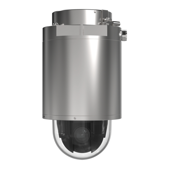
The “D” Series includes a full range of Stainless Steel or Anodized Aluminum camera stations specifically designed for Hazardous Area Applications. Spectrum’s D Series is the first Class I II III Division 1 rated dome style explosion proof housings and utilizes the most robust and advanced camera technologies available. The D Series was designed with the integrator in mind and offers features not available in competing EX camera systems available in the market. -
Page 7: Model Matrix
1= (S) Stainless Steel 316L Housing C= Internal Equipment Part Number from Manufacturer*** BD= Optional Breather drain model**** *Internal components and D Series must be approved by Spectrum **Internal Equipment Manufacturer Code below ***Must be approved and verified by Spectrum ****Models supplied with Breather Drains will have IP66 ingress protection level CODE “XX”... - Page 8 Labels Option A BREATHER DRAIN MODEL BREATHER DRAIN MODEL D201-1-Q6055 REV 4 105607312018 D SERIES INSTALLATION MANUAL REV-1...
- Page 9 STANDARDS & CERTIFICATIONS STANDARDS- The equipment is manufactured in accordance with the IECEX scheme, the ATEX Directive 94/9CE and with the following standards : IEC 60079-0:2011 IEC 60079-1:2014 IEC 60079-31:2013 IEC 60529:2013 EN 60079-0:2012 + A11:2013 EN 60079-1:2014 EN 60079-31:2014 EN 60529:1991 + A1:2000 + A2:2013 ANSI/ISA 60079-0:2013 ANSI/UL 60079-1:2015...
-
Page 10: Labels
DOCUMENT SYMBOLS The following symbols are used throughout this manual to alert users to potential hazards or important information. Failure to heed the warnings and cautions listed herein can lead to injury and equipment damage. Symbol Label Description Consists of conditions, practices, or procedures that WARNING: must be observed to prevent personal injury and/or equipment damage. -
Page 11: How To Use This Manual
How to use this Manual General Manual: This manual is intended to be used in conjunction with installed equipment manual from internal equipment manufacturer. Note: In the event of a conflict between the requirements of this general installation manual and the internal equipment manual, the safety and installation procedures described in this manual shall take precedence. -
Page 12: General Safety And Operating Information
General Safety and Operating Information: General safety and operating information applicable to electrical equipment installed within hazardous locations. This information must be understood by all persons installing, using, or maintaining the electrical equipment. This information is designed to aid personnel in safe installation, operation, and maintenance of the "D"... - Page 13 • Use a clean cloth dampened with pure water for cleaning. • Use only accessories that comply with the technical specification of the product. These can be provided by Spectrum or a third party. D201-1-Q6055 REV 4 105607312018 D SERIES...
- Page 14 General Safety and Operating Information: Installation: The installation must be realized in accordance with IEC/EN 60079-14 and/or in accordance with the national requirements. This equipment must be installed and used only by qualified personnel, having knowledge concerning electrical equipment for use in potentially explosive areas containing gas and/or dust.
-
Page 15: Specifications
SPECIFICATIONS CERTIFICATIONS of Model- D201-( )-Q6055-E CERT NO. FM17US0156 & FM18CA0103X Class I Division 1 Groups B,C,D T6, Ta = -20°C to +55°C Type 4X, IP66/67 Class II/III, Division 1, Groups E,F,G T6 Type 4X, IP66/67 Ta = -20°C to +55°C Class I, Zone 1, AEx/Ex db IIB+H2 T6 Gb Ta = -20°C to +55°C, Type 4X, IP66/67 Zone 21, AEx/Ex tb IIIC T85°C Db Ta = -20°C to +55°C, Type 4X, IP66/67 CERT NO. - Page 16 ALUMINUM 14 kg (32 lb) NOTE: Spectrum Camera Solutions, LLC is NOT responsible for any misuse or improper installation of product, assumes no liability for special or consequential damages caused by use or misuse or improper installation of its products sold and assumes no liability for injury from use or misuse or improper installation of its products or attached products.
-
Page 17: Unboxing
UNBOXING Optional SD-GK Anti-Galvanic corrosion isolation gasket kit for offshore use of Aluminum version Place camera on tabletop with dome facing down Remove rear (Terminal Housing) foam packaging to reveal hardware Remove hardware Install ring Gasket on terminal Housing *Optional SD-GK Aluminum version only Install wall mount with hardware removed from step 3 (Note: Apply Anti-seize to bolts.) Install wall mount gasket and hardware to secure mount to wall.*... -
Page 18: Hardware Bom
HARDWARE BOM 1- (QTY 1)EXTERNAL GROUND LUG 2- (QTY 3)M10 X 1.5 18-8 BOLT 3- (4 SETS) WEDGE LOCK WASHER 4- (QTY 1)D2005 Z-CLIP 5- SD-WM (WALL MNT. NOT INCLUDED) 6- M10X1.25 M10X1.5 ADAPTER 7- M10x1.25 hex nut D201-1-Q6055 REV 4 105607312018 D SERIES INSTALLATION MANUAL REV-1... -
Page 19: Wiring Entries
WIRING ENTRIES Conduit Entries are M20 x 1.5 Use appropriate adapter with nylon Washer or O-ring to keep ingress protection level. CAUTION: Ensure the Ethernet cable is disconnected from power source prior to wiring to the terminal block D201-1-Q6055 REV 4 105607312018 D SERIES INSTALLATION MANUAL REV-1... -
Page 20: Installation
INSTALLATION Ensure that power is off before attempting to connect and wire the camera 1. Use supplied M6 Hex tool to unscrew bolts and lock washers supplied on camera Figure 1. wall bracket installation 2. Make sure threads on camera and M10x 1.5 are free of dirt and debris. Place mount on camera and align holes and tighten bolts *add anti-seize for offshore installation 3. - Page 21 INSTALLATION 4. Use supplied M5 supplied Hex tool to loosen D1005 end cap by turning counterclockwise Figure 2. Removing D1005 cap 5. Set D1005 terminal cap in safe place 6. Route cable(s) into D1006 terminal housing junction box through user-supplied cable gland and seal using the recommended gland installation practices.
- Page 22 INSTALLATION 7. Connect the wiring using small screwdriver to push the open terminal block contact. Insert wires and remove screwdriver. Adhere to local electrical codes/laws. Table 1. Figure 5. Wire/Cable Connections Power Connection To "D" Series Camera Internal Ground TERMINAL WIRE NUMBER Position - 1...
- Page 23 INSTALLATION Figure 3. Conduit Entries are M20 x 1.5 Use appropriate Adapter With Nylon Washer or O-ring to keep ingress protection Figure 4. CAUTION: Ensure the ethernet cable is disconnected from power source prior to wiring to the terminal block D201-1-Q6055 REV 4 105607312018 D SERIES INSTALLATION MANUAL REV-1...
- Page 24 INSTALLATION 9. Ensure threads & gasket on D1005 cap and D1006 Terminal housing are free of dirt and debris. 10. Reinstall D1005 end cap using supplied M5 supplied Hex tool to tighten by turning clockwise until hand tight and gasket is seated Figure 7.
-
Page 25: Dimentional General Assembly
Dimensional General Assembly: D201-1-Q6055 REV 4 105607312018 D SERIES INSTALLATION MANUAL REV-1... -
Page 26: Dismantling & Maintenance
For more information about the server report, see the product´s setup pages or contact Spectrum support. The battery should not be replaced unless required. If required contact support@spectrumcamera.com... - Page 27 Doc No. Dxx-100107152019 Spectrum Camera Solutions, 2014/34/EU Spectrum Camera Solutions declares that under our sole responsibility that the product (s) listed below conform to the relevant provisions of 2014/34/EU of August 29, 2018 Notified Body FM Approvals Ltd. 1 Windsor Dials, Windsor, Berkshire, UK.
- Page 28 Doc No. Dxx-100107152019 Spectrum Camera Solutions, 2014/34/EU Spectrum Camera Solutions declares that under our sole responsibility that the product (s) listed below conform to the relevant provisions of 2014/34/EU of August 29, 2018 Notified Body FM Approvals Ltd. 1 Windsor Dials, Windsor, Berkshire, UK.
- Page 29 SD-WM WALL MOUNT D201-1-Q6055 REV 4 105607312018 D SERIES INSTALLATION MANUAL REV-1...
- Page 30 SD-PMA POLE MOUNT ADAPTER HARDWARE QTY 4 7/8-20 18-8 Bolts QTY 2 12in all thread with nuts and washers QTY 2 A1612 sides D201-1-Q6055 REV 4 105607312018 D SERIES INSTALLATION MANUAL REV-1...
- Page 31 SD-CM CORNER MOUNT HARDWARE- QTY 4 7/8-20 18-8 Bolts D201-1-Q6055 REV 4 105607312018 D SERIES INSTALLATION MANUAL REV-1...
- Page 32 SD-VM VIBRATION MOUNT HARDWARE- QTY 4 7/8-20 18-8 Bolts FRONT D201-1-Q6055 REV 4 105607312018 D SERIES INSTALLATION MANUAL REV-1...
- Page 33 SD-SO STANDOFF MOUNT HARDWARE- QTY 4 7/8-20 18-8 Bolts FRONT BACK D201-1-Q6055 REV 4 105607312018 D SERIES INSTALLATION MANUAL REV-1...
- Page 34 ASSEMBLY MOUNTS SD-CM+SD-VM+SD-SO+ SD-PMA SD-CM+SD-PMA D201-1-Q6055 REV 4 105607312018 D SERIES INSTALLATION MANUAL REV-1...
Need help?
Do you have a question about the D201 Q6055-E-BD Series and is the answer not in the manual?
Questions and answers