Table of Contents
Advertisement
Quick Links
This manual covers to the following remote control equipment products operation, installation and programming::
Equipment Type
UMB100HShet
AN200HShet
UMB100HRhet
All above listed equipment products include the same receiver model featuring:
One galvanic separated relay output with NC/NO terminals,
One OC (open collector) transistor type output for acoustic indication of relay output switch-over,
Two color LED indicating state of the relay output,
Comfortable wide range of AC and DC power supply voltages,
Highly sensitive and selective superhet receiver module,
Up to 112 hand and keyfob remote control transmitters (further referred to as "remotes") memory capacity,
KEELOQ® transmission dynamic encoding system.
Receiver Operation Modes
Receiver allows various operation features depending on selection made by jumpers JP1 & JP2 and programming Monostable (pulse) or Bistable
(on/off) relay output mode (step 2 and 3 of programming procedures), as shown in Table 1, below :
Jumpers State
A. Pressing transmitter button sets receiver's relay output on for
JP2 On
(3)
JP1
programmed time period. Next pressing of the button, while
JP2 Off,
C. Receiver relay output is set on for as long as transmitter button
JP1 On
is pressed and sets off, after short delay
JP2 Off
D. Pressing transmitter button 1 sets the output on. Pressing
JP1 Off
button 2 sets output off. If button 2 is not pressed, relay output
(1)
Output relay Monostable Mode (pulse) or Bistable Mode (on/off) is programmed in steps 2 and 3 of programming procedures.
(2)
Delayed output set off reduces risk of unwanted interruptions in output set on continuity, due to interferences caused e.g. electric motors.
Precise setting of this short delay timing is facilitated by programming 8-fold longer time delay of that needed. Example: to obtain 0.5s set
off delay, programmed delay of 4..5s delay must be made (0.5 x 8=4).
Number of remote control transmitters that can be used in this mode is limited to 20.
(3)
In modes A & B jumper JP1 selects timing of switch-over signal pulses at output S: jumper On – 0.25s pulse, jumper Off – 0.50s pulse.
Longer timing of switch-over signal pulses are necessary for certain acoustic signaling devices in which shorter pulses are not recognized
properly.
(4)
This mode requires use of hand transmitter with two or more buttons.
KEELOQ® Encoding System
In the system, newly encoded control signal is generated and sent each time transmitter button is pressed. Receiver monitors code changes and
responds to signals with new code only. Once received code will not be accepted second time. This allows protection of radio transmission sig-
nals from deliberate grabbing and decoding.
Receiver Memory
As each transmitter generates specific dynamic code, receiver must "learn" and memorize individual coding way of every transmitter that will
operate with the receiver. Therefore, receiver's memory capacity is limited. In case of receiver UMB100HRhet capacity is limited to 112 trans-
th
mitters. Learning 113
transmitter would delete first transmitter in memory, etc. Eliminating one or more lost or stolen transmitters from receiv-
er's memory requires deleting all transmitters and learning all remaining transmitters again. Deleting one or more transmitters from receiver's
memory is possible only if the transmitters are available.
Receiver Relay Output
Receiver is equipped with galvanic isolated relay output with NO (normally open) and NC (normally closed) wiring terminals. Details are shown
on installation diagram included in this manual.
Transistor Output
Receiver features one open collector type (OC) transistor signaling output for connecting to external acoustic siren or light strobe. The output
generates two pulses on receiver's relay output set ON and one pulse on relay output set OFF. Two pulses are generated also when pressed
transmitter's button is used to prolong timing of output set on in monostable mode only (mode A in Table 1). In operation modes D and E (Table
1), in which button 1 sets output on and button 2 sets output off, two pulses are generated each time button 1 is pressed and one pulse each time
button 2 is pressed.
LED Indication
Receiver is equipped with two color LED signaling power supply connection and status of relay output. It lights Red when power is connected
and relay output is not activated. When relay output is activated it lights Green for as long as the output stays on.
Receiver Installation
Receiver is designed to operate indoors only. Place of installation should be dry and away from electromagnetic power lines, radio transmitters,
metal screening and other devices that may cause interference and reduce operation range. Receiver should be installed well above floor/ground
level. It is recommended to test practical operating range of transmitter-receiver set prior to firm installation. Level of hand transmitter signals
and unwanted radio interference signals can be tested using optional Elmes RFM indicator.
e-mail: elmes@elmes.pl internet: www.elmes.pl
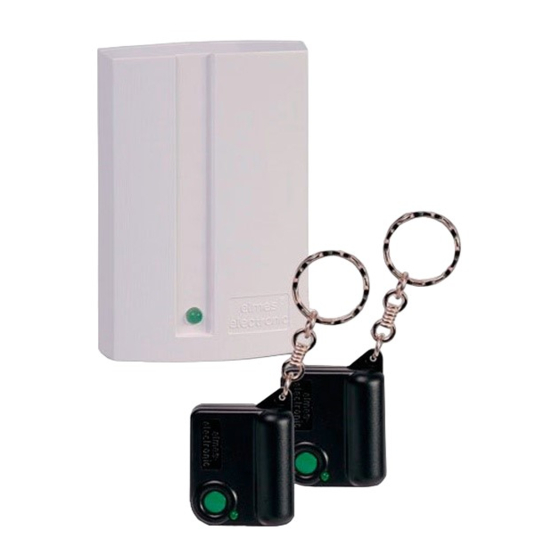
ONE OUTPUT REMOTE CONTROL SETS WITH DYNAMIC CODE:
UMB100HShet, AN200HShet – receivers with hand transmitters
UMB100HRhet – receiver only
Set Content
receiver UMB100HRhet + 2 remotes UMB100HT
receiver UMB100HRhet + 1 remote AN200HT
UMB100HRhet – receiver only
Monostable Mode
output is on, prolongs set on time of the output.
sets off after programmed time period
Table 1
(1)
B. Each pressing of remote transmitter button sets receiver relay
(2)
, on button release.
E. Pressing transmitter button 1 sets output on. Pressing button
(4)
Maximum Operating Range
100 m
200 m
-
(1)
Bistable Mode
output on and off alternately (on/off mode).
Not available
2 sets output off.
Elmes Elektronik 03.2010. All rights reserved
(EN)
Advertisement
Table of Contents

Subscribe to Our Youtube Channel
Related Manuals for Elmes Electronic UMB100HShet


Summary of Contents for Elmes Electronic UMB100HShet
- Page 1 ONE OUTPUT REMOTE CONTROL SETS WITH DYNAMIC CODE: UMB100HShet, AN200HShet – receivers with hand transmitters UMB100HRhet – receiver only (EN) This manual covers to the following remote control equipment products operation, installation and programming:: Equipment Type Set Content Maximum Operating Range...
- Page 2 Elmes Electronic shall not be liable for any personal or material damage or loss resulting from any of its products direct, indirect or partial use or failure to operate properly.
Need help?
Do you have a question about the UMB100HShet and is the answer not in the manual?
Questions and answers