Table of Contents
Advertisement
Quick Links
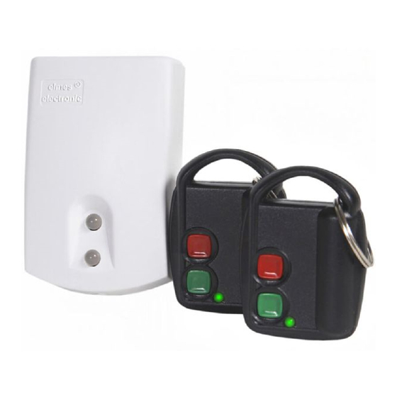
TWO RELAY OUTPUTS REMOTE CONTROL SETS WITH DYNAMIC CODE
This manual covers the following remote control products operation, installation and programming:
Equipment Type
U2HS
U2HSL
U2HR
Above specified products differ in number and type of used hand transmitters. All use the same receiver which features are described below.
Easy allocation of hand transmitter buttons to control any receiver output
Receiver is provided with two on-board programming switches: PRG1 for programming output one and PRG2 for programming output two.
Both programming switches allow learning any hand transmitter button to control respective output. Moreover, the same button can control other
output of the receiver, or two hand transmitter buttons can be learned to control one receiver output. These features allow the following control
possibilities (examples):
Some one button hand transmitters control operation of receiver output one, while other one button transmitters control output two.
Any button of multi-button transmitter controls receiver output one, while any other button of the same transmitter controls output two.
Two buttons of the same transmitter control one receiver output: one button sets the output on, while other sets the output off.
One transmitter button controls two receiver outputs simultaneously, e.g. controlling two equipment units with galvanic separation.
Remark: full flexibility of allocating any hand transmitter buttons to control any receiver outputs refers to use of Elmes transmitters with 1 to 4
control buttons and multi-channel hand transmitter STX. In the case of transmitters CH8H and CH32H certain limitations apply: buttons of two
adjacent control channel banks cannot be learned to the same receiver, e.g. buttons from banks 1 & 2, or 3 & 4, etc.
Receiver outputs operation modes
Receiver outputs can operate in one of many modes selected by jumpers JP1 and JP2 and individually programmed to each output monostable
(pulse), or bistable (on/off) timing modes (see pt 3 & 4 of programming procedures and table below). These allow range of solutions for various
remote control applications, such as (examples):
Pressed transmitter button sets receiver output on for programmed time. Next pressed, while in output set on state, prolongs set on time
(mode A in Table below);
Pressed transmitter button sets receiver output permanent on. Next pressed, sets output off (modes B, D & F);
Pressed transmitter button sets receiver output on for programmed time. Next pressed, while in output set on state, sets output off (m.E);
Pressed transmitter button sets receiver output permanent on (mode H), or for programmed time (mode G). Next pressed, while in output
set on state, sets output off. This mode differs from two earlier described by that, it does not allow two outputs to be set on simultaneous-
ly. If output one is on and transmitter button learned to output two is pressed then output one sets off. Next pressed the same button sets
output two on. This mode is used for electric motors control;
As above, but remote control is performed with the use of single transmitter button only. Subsequent use of the same transmitter button
sets on output one, sets the output off, sets on output two, sets the output off. This mode is also used for electric motor control (m. G & H);
Pressed transmitter button sets output on. Subsequent use of the same button does not change output status. The output sets off when other
button of the transmitter is pressed. This mode (B & D) is useful for secure switching on and off remote equipment not visible to operator.
Pressed transmitter button sets receiver output on for as long as the button is pressed. Released button sets receiver output off. This remote
control mode is frequently used by failed/damaged car transporter operators (mode C).
Jumper Status
A. Pressing transmitter button sets receiver's relay output on for
JP1 On
JP2 On
programmed time period. Next pressing of the button, while
JP1 On
C. Receiver relay output is set on for as long as transmitter button
JP2 Off
is pressed and sets off, after short delay, on button release
JP1 Off
E. Subsequent pressing transmitter button set output on and off. If
JP2 On
JP1 Off
G. As above, except that two receiver outputs cannot be set on
JP2 Off
(1)
Output relay Monostable Mode (pulse) or Bistable Mode (on/off) is programmed in steps 3 and 4 of programming procedures.
(2)
Delayed output set off reduces risk of unwanted interruptions in output set on continuity, due to interferences caused e.g. electric motors. Precise setting of
this short delay timing is facilitated by programming 8-fold longer time delay of that needed. Example: to obtain 0.5s set off delay, programmed delay of 4..5s
delay must be made initially (0.5 x 8=4).
(3)
These modes also allow single transmitter button control of two receiver outputs. Subsequent use of transmitter button sets output one, sets the output off, sets
output two on, sets the output off, etc. To obtain that transmitter button must be learned to only one receiver output.
(4)
If transmitter button is learned to one receiver output, then subsequent pressing of this button alternately set on and set off that output. If two transmitter
buttons (1 & 2 or 3 & 4) are learned to one receiver output, then odd buttons (1 & 3) always sets output on while even buttons sets the output off.
(5)
Number of remote control transmitters that can be used in this mode is limited to 20.
KEELOQ® Encoding System
In the system, newly encoded control signal is generated and sent each time transmitter button is pressed. Receiver monitors code changes and
responds to new code signals only. Once received code will not be accepted second time. This allows protection of radio transmission signals
from deliberate code grabbing and unauthorized use.
Receiver Relay Output
Receiver is equipped with galvanic isolated relay output with NO (normally open) and NC (normally closed) three wiring terminals – one com-
mon. The output switches over on received set on signal. Details are shown on installation diagram included in this manual.
LED Indication
Receiver is equipped with two LEDs. Upper LED indicates power supply in red and switches to green on output 1 set on. Bottom LED is off on
output 2 set off and shines green on output 2 set on.
Signalling Output S
Receiver features open collector type (OC) signalling output S for connecting to external acoustic siren or light strobe. The output generates two
pulses shorting to receiver's ground (-V) on any relay output set ON and one pulse on relay output set OFF in 0.5s pulse rate. Two pulses are
e-mail: elmes@elmes.pl internet: www.elmes.pl
Models: U2HS, U2HSL, U2HR (receiver only)
receiver U2HR + 2 transmitters DWB100HT
receiver U2HR + 1 transmitter DW200HT
U2HR – receiver only
Table of relay outputs available operation modes
Monostable Mode
output is on, prolongs set on time of the output.
button is not used output sets off after programmed time.
simultaneously – function useful for motor control
Set Content
(1)
B. Each pressing of remote transmitter button sets receiver relay
output on and off alternately (on/off mode), or one button sets
(2,5)
F. Subsequent pressing transmitter button set output on and off.
H. As above, except that two receiver outputs cannot be set on
(3)
Operating Range
100 m
200 m
-
Bistable Mode
on only while other sets off only
(4,5)
D. As above
simultaneously – function useful for motor control
Elmes Elektronik 09.2013. All rights reserved
(EN)
(1)
(4)
(3)
Advertisement
Table of Contents

Related Manuals for Elmes Electronic U2HS


Summary of Contents for Elmes Electronic U2HS
- Page 1 TWO RELAY OUTPUTS REMOTE CONTROL SETS WITH DYNAMIC CODE Models: U2HS, U2HSL, U2HR (receiver only) (EN) This manual covers the following remote control products operation, installation and programming: Equipment Type Set Content Operating Range U2HS receiver U2HR + 2 transmitters DWB100HT...
- Page 2 Elmes Electronic shall not be liable for any personal or material damage or loss resulting from any of its products direct, indirect or partial use or failure to operate properly.
Need help?
Do you have a question about the U2HS and is the answer not in the manual?
Questions and answers