Table of Contents
Advertisement
Quick Links
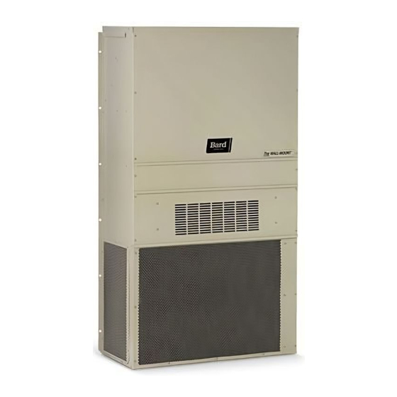
INSTALLATION INSTRUCTIONS
WALL-MOUNTED PACKAGED
Bard Manufacturing Company, Inc.
Bryan, Ohio 43506
www.bardhvac.com
AIR CONDITIONER
Models:
WA3S3-A
WA3S3-B
WA3S3-C
WA4S3-A
WA4S3-B
WA4S3-C
WA5S3-A
WA5S3-B
WA5S3-C
WL3S2-A
WL3S2-B
WL3S2-C
WL4S2-A
WL4S2-B
WL4S2-C
WL5S2-A
WL5S2-B
WL5S2-C
Manual:
Supersedes: 2100-526G
Date:
2100-526H
7-13-18
Page
1 of 24
Advertisement
Table of Contents

Related Manuals for Bard WA3S3-A


Summary of Contents for Bard WA3S3-A
- Page 1 WALL-MOUNTED PACKAGED AIR CONDITIONER Models: WA3S3-A WL3S2-A WA3S3-B WL3S2-B WA3S3-C WL3S2-C WA4S3-A WL4S2-A WA4S3-B WL4S2-B WA4S3-C WL4S2-C WA5S3-A WL5S2-A WA5S3-B WL5S2-B WA5S3-C WL5S2-C Bard Manufacturing Company, Inc. Manual: 2100-526H Bryan, Ohio 43506 Supersedes: 2100-526G Date: 7-13-18 www.bardhvac.com Page 1 of 24...
-
Page 2: Table Of Contents
CONTENTS Getting Other Information and Publications ..3 Start Up ..............13 For more information contact these publishers ..3 General ............. 13 Topping Off System Charge ......... 13 Wall Mount General Information ......4 Safety Practices ..........13 Air Conditioner Wall Mount Model Nomenclature ..4 Important Installer Note ........ -
Page 3: Getting Other Information And Publications
GETTING OTHER INFORMATION AND PUBLICATIONS For more information, contact these publishers: These publications can help when installing the air conditioner or heat pump. These can usually be found at the local library or purchase them directly from the ACCA Air Conditioning Contractors of America publisher. -
Page 4: Wall Mount General Information
WALL MOUNT GENERAL INFORMATION AIR CONDITIONER WALL MOUNT MODEL NOMENCLATURE – MODEL CONTROL MODULES REVISION NUMBER (see Spec. Sheet S3378) WA – 3 WA – Right Hand COIL OPTIONS WL – 2 WL – Left Hand X – Standard 1 – Phenolic Coated Evaporator VOLTS &... -
Page 5: Figure 1 Unit Dimensions
TABLE 2 DIMENSIONS OF BASIC UNIT FOR ARCHITECTURAL & INSTALLATION REQUIREMENTS (NOMINAL) Supply Return Width Depth Height Unit WA/L3S* 84.875 31.66 32.68 26.94 34.69 32.43 23.88 WA/L4S 42.075 22.432 9.88 29.88 15.88 29.88 43.88 19.10 30.00 3.37 42.88 10.00 1.44 16.00 1.88 94.875 41.66 42.68 36.94 44.69 42.43... -
Page 6: Table 3 Electrical Specifications
Manual 2100-526H Page 6 of 24... -
Page 7: Shipping Damage
Any grille that meets the 5/8 inch louver criteria, may recommended guide, they do not supersede any be used. It is recommended that Bard Return Air national and/or local codes in any way. Authorities Grille Kit RG-5 or RFG-5 be installed when no return having jurisdiction should be consulted before the duct is used. -
Page 8: Installation
INSTALLATION WALL MOUNTING INFORMATION 3. Locate and mark lag bolt locations and bottom mounting bracket location. See Figure 4. 1. Two holes, for the supply and return air openings, 4. Mount bottom mounting bracket. must be cut through the wall as shown in Figure 3. 5. -
Page 9: Figure 2 Mounting Instructions
The unit rating plate lists a “Maximum Time Delay To convert for the locking capability, bend the tab Relay Fuse” or circuit breaker that is to be used with located in the bottom left hand corner of the disconnect the equipment. The correct size must be used for opening under the disconnect access panel straight proper circuit protection and also to assure that there out. -
Page 10: Figure 3 Wall-Mounting Instructions
FIGURE 3 WALL-MOUNTING INSTRUCTIONS SEE FIGURE 3 – MOUNTING INSTRUCTIONS WALL STRUCTURE FACTORY SUPPLIED RAIN FLASHING. MOUNT ON UNIT BEFORE INSTALLATION SUPPLY AIR SUPPLY AIR SUPPLY AIR DUCT OPENING OPENING RETURN AIR RETURN AIR RETURN AIR OPENING OPENING OPENING BOTTOM MOUNTING WOOD OR STEEL SIDING BRACKET. -
Page 11: Figure 5 Common Wall-Mounting Instructions
FIGURE 5 COMMON WALL-MOUNTING INSTALLATIONS SUPPLY DUCT MAY BE LOCATED IN AN ATTIC OR BELOW CEILING RAFTERS AS SHOWN RAIN RAIN FLASHING RAFTERS FLASHING RAFTERS FINISHED CEILING SURFACE SUPPLY AIR DUCT SUPPLY AIR DUCT FINISHED CEILING SURFACE W/ GRILLE RETURN AIR RETURN AIR OPENING W/ GRILLE OPENING W/ GRILLE... -
Page 12: Wiring - Low Voltage Wiring
8403-058 Electronic Non-Programmable (TH5220D1151) Auto or Manual changeover THERMOSTATIC CONTROL FOR DUAL UNIT APPLICATION Thermostat Predominate Features Bard Specifications 2-Unit/2-Stage Heat/2-Stage Cool TEC40 See Spec. Sheet S3353 Controller 2-Unit/2-Stage Heat/2-Stage Cool MC3000 See Spec. Sheet S3379 Controller with Option Alarms... -
Page 13: Start Up
Purge with small amount of nitrogen when inserting plugs. TOPPING OFF SYSTEM CHARGE If a leak has occurred in the system, Bard Manufacturing recommends reclaiming, evacuating (see criteria above), and charging to the nameplate charge. Topping off the system charge can be done without problems. -
Page 14: Figure 7 Start-Up Label
IMPORTANT INSTALLER NOTE HIGH AND LOW PRESSURE SWITCH For improved start-up performance, wash the indoor All models covered by this manual are supplied with coil with a dishwasher detergent. a remote reset high pressure switch and low pressure switch. If tripped, this pressure switch may be reset by turning the thermostat off then back on again. -
Page 15: Service Hints
SERVICE HINTS Adjustable Delay On Make And Break Timer On initial power up or anytime power is interrupted to 1. Maintain clean air filters at all times. Also, do the unit, the delay on make period begins, which will not close off or block supply and return air be 2 minutes plus 10% of the delay on break setting. -
Page 16: Adjustments
Alarm Relay Output PHASE MONITOR Alarm terminal is output connection for applications All units with three phase scroll compressors are where alarm relay is employed. This terminal is equipped with a 3-phase line monitor to prevent powered whenever compressor is locked out due to HPC compressor damage due to phase reversal. -
Page 17: Figure 8 Fan Blade Setting
SERVICE COMPRESSOR SOLENOID FAN BLADE SETTING DIMENSIONS (See Sequence of Operation on page 15 for function.) Shown in the drawing below are the correct fan blade A nominal 24-volt direct current coil activates the setting dimensions for proper air delivery across the internal compressor solenoid. -
Page 18: R-410A Refrigerant Charge
R-410A REFRIGERANT CHARGE The following pressure tables show nominal pressures for the units. Since many installation specific This unit was charged at the factory with the quantity of situations can affect the pressure readings, this refrigerant listed on the serial plate. AHRI capacity and information should only be used by certified technicians efficiency ratings were determined by testing with this as a guide for evaluating proper system performance. -
Page 19: Pressure Chart
TABLE 8 COOLING PRESSURE – (ALL TEMPERATURES °F) HIGH CAPAPACITY COOLING AIR TEMPERATURE ENTERING OUTDOOR COIL DEGREE F Return Air Temp Model Pressure 50˚F 55˚F 60˚F 65˚F 70˚F 75˚F 80˚F 85˚F 90˚F 95˚F 100˚F 105˚F 110˚F 115˚F (DB/WB) 75˚ DB Low Side 62˚... -
Page 20: Troubleshooting Ge Ecm ™ Motors
TROUBLESHOOTING GE ECM ™ MOTORS Symptom Cause/Procedure CAUTION: • Noisy blower or cabinet • Check for loose blower housing, panels, etc. Disconnect power from unit before removing or replacing • High static creating high blower speed? connectors, or servicing motor. To avoid electric shock from - Check for air whistling through seams in the motor’s capacitors, disconnect power and wait at least 5 ducts, cabinets or panels... -
Page 21: Figure 9 Control Disassembly
Replacing ECM Control Module 8b. IF REPLACING AN ECM 2.3 CONTROL WITH AN ECM 2.3 CONTROL, the plastic tab and shorter through-bolts are not needed. The To replace the control module for the GE variable-speed indoor blower control can be oriented in two positions 180° apart. MAKE SURE THE motor you need to take the following steps: ORIENTATION YOU SELECT FOR REPLACING THE CONTROL ASSURES THE 1. -
Page 22: Table 9 Indoor Blower Performance
TABLE 9 INDOOR BLOWER PERFORMANCE Model Rated ESP MAX ESP Continuous Rated 1st Rated 2nd 5-10KW 15-20 KW Stage CFM Stage CFM WA/L3S* 0.15 0.80 1100 1100 1400 WA/L4S* 0.20 0.80 1100 1500 1100 1500 WA/L5S* 0.20... -
Page 23: Optional Accessories
TABLE 11 OPTIONAL ACCESSORIES MODEL DESCRIPTION EHWA4S-A05 Heater Package EHWA4S-A10 Heater Package EHWA4S-A15 Heater Package EHWA4S-A20 Heater Package EHWA5S-A05 Heater Package EHWA5S-A08 Heater Package EHWA5S-A10 Heater Package EHWA5S-A15 Heater Package EHWA5S-A20 Heater Package EHWA3S-B06 Heater Package EHWA5S-B06 Heater Package EHWA5S-B09 Heater Package EHWA5S-B15 Heater Package... -
Page 24: Table 12 Opt. Accessories (Wl)
TABLE 12 OPTIONAL ACCESSORIES MODEL DESCRIPTION EHWA4S-A05L Heater Package EHWA4S-A10L Heater Package EHWA4S-A15L Heater Package EHWA4S-A20L Heater Package EHWA5S-A05L Heater Package EHWA5S-A08L Heater Package EHWA5S-A10L Heater Package EHWA5S-A15L Heater Package EHWA5S-A20L Heater Package EHWA3S-B06L Heater Package EHWA5S-B06L Heater Package EHWA5S-B09L Heater Package EHWA5S-B15L Heater Package...
Need help?
Do you have a question about the WA3S3-A and is the answer not in the manual?
Questions and answers