Sign In
Upload
Download
Table of Contents
Contents
Add to my manuals
Delete from my manuals
Share
URL of this page:
HTML Link:
Bookmark this page
Add
Manual will be automatically added to "My Manuals"
Print this page
×
Bookmark added
×
Added to my manuals
Manuals
Brands
Bard Manuals
Air Conditioner
WA301
Installation instructions manual
Bard WA301 Installation Instructions Manual
Wall mounted packaged air conditioners
Hide thumbs
1
Table Of Contents
2
3
4
5
6
7
8
9
10
11
12
13
14
15
16
17
18
19
page
of
19
Go
/
19
Contents
Table of Contents
Troubleshooting
Bookmarks
Table of Contents
Table of Contents
Getting Other Information and Publications
For more Information
Contact These Publishers
Wall Mount General Information
Air Conditioner Wall Mount Model Nomenclature
Table 1 Electrical Specifications
Figure 1 Unit Dimensions
Table 2 Dimensions of Basic Unit
Table 3 Electric Heat Table
Shipping Damage
General
Duct Work
Filters
Fresh Air Intake
Condensate Drain
Figure 2 Blower Damper Assembly
Installation Instructions
Wall Mounting Information
Mounting the Unit
Top Outlet Only
Wiring - Main Power
Wiring - Low Voltage Wiring
Table 4 Operating Voltage Range
Table 5 Thermostat Wire Size
Table 6 Wall Thermostat and Subbase Combinations
Figure 3 Mounting Instructions
Figure 4 Electric Heat Clearances
Figure 5 Wall-Mounting Instructions
Figure 6 Wall-Mounting Instructions
Figure 7 Common Wall-Mounting Installations
Figure 8 Low Voltage Wiring
Figure 9 Start up Label
Start up
Important Installer Note
Crankcase Heaters
Service Hints
Sequence of Operation
Compressor Control Module
Adjustments
Pressure Service Ports
Figure 10 Fan Blade Setting
Troubleshooting
Fan Blade Setting Dimensions
Removal of Fan Shroud
Refrigerant Charge
Table 7 Fan Blade Dimensions
Table 8 Suction Line Temperatures
Table 9 Indoor Blower Performance
Table 10 CFM and ESP
Pressure Table
Table 11 Maximum ESP of Operation
Electric Heat Only
Table 12 Cooling Pressure
Optional Accessories
Table 13 Optional Accessories
Advertisement
Quick Links
1
Table 1 Electrical Specifications
2
Air Conditioner Wall Mount Model Nomenclature
3
Filters
4
Wiring - Main Power
5
Wiring - Low Voltage Wiring
6
Refrigerant Charge
Download this manual
INSTALLATION
INSTRUCTIONS
AIR CONDITIONER
Models:
Bard Manufacturing Company
Bryan, Ohio 43506
Since 1914...Moving ahead just as planned.
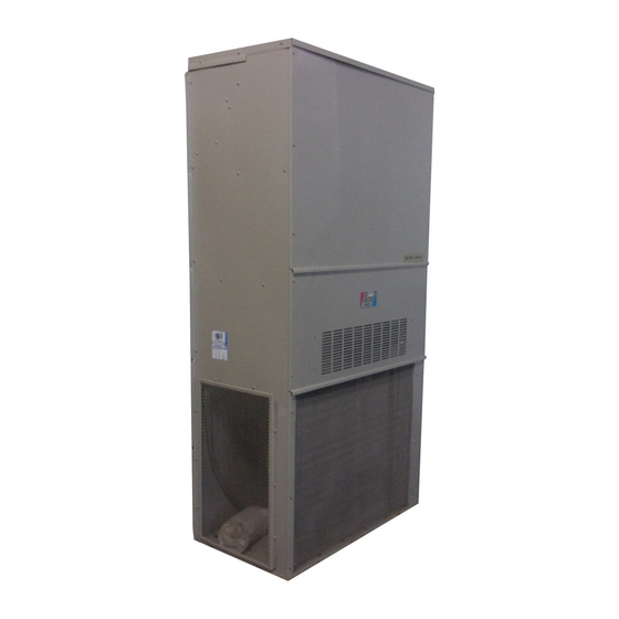
WALL MOUNTED
PACKAGED
WA301, WA361
MIS-656
Manual No.:
Supersedes:
File:
Date:
2100-192M
2100-192L
Volume III, Tab 16
05-13-02
© Copyright 2002
Table of
Contents
Previous
Page
Next
Page
1
2
3
4
5
Advertisement
Table of Contents
Need help?
Do you have a question about the WA301 and is the answer not in the manual?
Ask a question
Questions and answers
Related Manuals for Bard WA301
Air Conditioner Bard WA381 Installation Instructions Manual
Wall mounted package air conditioners (21 pages)
Air Conditioner Bard WA605 Installation Instructions Manual
Wall mounted package air conditioners (21 pages)
Air Conditioner Bard WA423 Installation Instructions Manual
Wall mounted package air conditioners (21 pages)
Air Conditioner Bard WA302 Installation Instructions Manual
Wall mounted packaged air conditioner (19 pages)
Air Conditioner Bard WA3S Manual
S series step capacity air conditioners (12 pages)
Air Conditioner Bard WA361 Installation Instructions Manual
Wall mounted packaged air conditioners (19 pages)
Air Conditioner Bard WA3S1 Installation Instructions Manual
(24 pages)
Air Conditioner Bard WA3S3 Installation Instructions Manual
(24 pages)
Air Conditioner Bard WA421 Installation Instructions Manual
Wall mounted package air conditioners (21 pages)
Air Conditioner Bard WA611 Installation Instructions Manual
Bard wall mounted packaged air conditioner installation instructions models: wa611/wa701-b/wa701-c/wa702-a/wa721 (26 pages)
Air Conditioner Bard WA121 Installation Instructions Manual
Wall mounted packaged air conditioners (17 pages)
Air Conditioner Bard WA181 Installation Instructions Manual
Wall mounted packaged (18 pages)
Air Conditioner Bard WA182 Installation Instructions Manual
Wall mounted packaged air conditioner (18 pages)
Air Conditioner Bard WA Series Installation Instructions Manual
Wall mount air conditioner (72 pages)
Air Conditioner Bard W36ABRC Installation Instructions Manual
Wall mount air conditioner (42 pages)
Air Conditioner Bard WA253 Series Installation Instructions Manual
Wall mounted packaged air conditioner (16 pages)
This manual is also suitable for:
Wa361
Table of Contents
Print
Rename the bookmark
Delete bookmark?
Delete from my manuals?
Login
Sign In
OR
Sign in with Facebook
Sign in with Google
Upload manual
Upload from disk
Upload from URL


Need help?
Do you have a question about the WA301 and is the answer not in the manual?
Questions and answers