Advertisement
Available languages
Available languages
Fig./Abb. 1
1:2 DIN
1:1 M200E-SMB
Sollevare
Levantar
Anheben
Fig./Abb. 2
Fig./Abb. 3
Fig./Abb. 4
DOP-IOD074
0905
EN54-17: 2005
21
EN54-18: 2005
N200-501-00
22 mm
60°C
-20°C
2
1
Rotate
Plug
Ruotare
Inserire
Girar
Conectar
Drehen
Einhaken
Clip / Agganciare
3
Acoplar / Einrasten
3
1
Lift
Push down
Premere
Precionar
hacia abajo
Runterdrücken
2
Rotate / Ruotare
Girar / Drehen
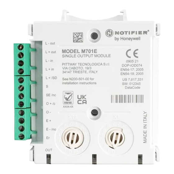
M701E
M701E
(i)
+
(iii)
Fig./Abb. 5
Notifier by Honeywell
Pittway Tecnologica S.r.l
Via Caboto 19/3
34147 Trieste, Italy
Notifier by Honeywell, 140 Waterside Road, Hamilton Industrial Estate, Leicester, LE5 1TN, UK
M701E
EN
FOR THE M701E OUTPUT MODULE
This manual is intended as a quick reference installation guide. Please refer to the
control panel manufacturers installation manual for detailed system information.
The M700 series of modules are a family of microprocessor controlled interface
devices permitting the monitoring and/or control of auxiliary devices. The M701E is
an output module that allows the control of auxiliary devices such as fire shutters or
sounders.
A single tri-colour LED indicates the status of the module. In normal conditions, the
LED can be set by command from the control panel to blink green when the module is
polled. When the control panel switches the relay to the energised state the LED can
be set to continuous green.
SPECIFICATIONS
Operating Voltage Range:
Maximum Standby Current
LED Current (Red):
LED Current (Yellow):
Isolator features:
Humidity:
Maximum Wire Gauge
INSTALLATION
Note: These modules must only be connected to control panels using compatible
proprietary analogue addressable communication protocols for monitoring and control.
M700 series modules can be mounted in several ways (See Figure 1):
1:1 An M200E-SMB custom low profile surface-mounting box. The SMB Base is
affixed to mounting surface, and then the module and cover are screwed onto
the base using the two screws supplied. Box dimensions: 132 mm (H) x 137 mm
(W) x 40 mm (D)
1:2 The DIN bracket on top allows mounting onto standard 35 mm x 7.5 mm "Top Hat"
DIN rail inside a control panel or other suitable enclosure. Install and remove as
shown in Figure 1:2.
Wiring to all series M700 modules is via plug in type terminals capable of supporting
conductors up to 2.5 mm²
Disconnect loop power before installing modules or sensors.
The module address is selected by means of rotary decade address switches (see
Figure 4). A screwdriver should be used to rotate the wheels to select the desired
address, either from the front or the top of the module. (Note: The number of addresses
available will be dependent on panel capability, check the panel documentation for
information on this.)
Short Circuit Isolators
All M700 series modules are provided with short circuit monitoring and isolators on the
intelligent loop. If required the isolators may be wired out of the loop to facilitate the
use of the modules on high current loaded loops, for example if sounders are used.
To achieve this, the loop out positive should be wired to terminal 5 rather than terminal
2. See the relevant wiring diagram for details.
M701E WIRING
The M701E can be wired for either Supervised (Figure 2) or Non-Supervised
(Figure 3) operation respectively.
Observe precautions when handling and making connections
M701E Single Output Module with Supervised Output
When the module is used in supervised mode and power is supplied to the module,
a switched negative input on terminal 12 can be used to signal an external fault
condition, such as a power supply fault. Loss of power is also supervised in this mode
such that if the supply voltage falls below 7V a fault indication is achievable. Note that
the use of this fault mode is dependant on panel software. Please contact the panel
(ii)
manufacturer for further details.
PSU monitoring is not available when the module switches the output to Alarm.
Wire as follows (see Figure 2):
a: T1 Loop Output -. b: T2 Loop Output +. c: T3 Loop Input -. d: T4 Loop Input +
e: T5 Loop Output +. If short circuit isolation is not required, loop output+ should be
wired to terminal 5 and not 2. Terminal 5 is internally connected to terminal 4.
f: To enable output circuit supervision, the link supplied must be fitted across
terminals 6 and 7, and the load must be polarised.
INSTALLATION INSTRUCTIONS
15 to 32VDC (Min 16.5VDC for LED operation)
160 µA - No Communication
1.5 mA
5.5 mA
see S00-7100
5% to 95% relative humidity (non-condensing)
2.5 mm²
CAUTION
CAUTION
Electrostatic Sensitive Device
I56-4405-001
Advertisement
Table of Contents

Related Manuals for Honeywell NOTIFIER M701E


Summary of Contents for Honeywell NOTIFIER M701E
- Page 1 To enable output circuit supervision, the link supplied must be fitted across Via Caboto 19/3 EN54-18: 2005 terminals 6 and 7, and the load must be polarised. 34147 Trieste, Italy Notifier by Honeywell, 140 Waterside Road, Hamilton Industrial Estate, Leicester, LE5 1TN, UK N200-501-00 I56-4405-001...
- Page 2 h: External power supply max. 32V DC, min. 7V DC. In supervised mode, the module ATTENZIONE monitors the power supply voltage across terminals 10 and 11 to ensure it does Dispositivo sensibile alle scariche elettrostatiche not drop below 7V, and also monitors for a switched negative fault signal from Effettuare i collegamenti e maneggiare con cautela the power supply to terminal 12 (optional).
- Page 3 El M701E se puede conectar para que funcione Con Supervisión (Figura 2) o Sin Supervisión (Figura 3). PRECAUCIÓN Equipo sensible a la electricidad estática Tome las precauciones necesarias al manejar el equipo y hacer las conexiones N200-501-00 Honeywell Life Safety Iberia, S.L. C/ Pau Vila, 15-19, 08911 Badalona (Barcelona) Espana I56-4405-001...
- Page 4 INSTALLATIONSANLEITUNG h: Externes netzteil max. 32VDC, min. 7VDC. Im überwachten Betrieb wird die Betriebsspannung zwischen den Klemmen 10 und 11 überwacht und FÜR DIE MODULE M701E geprüft, dass der Wert 7V nicht unterschritten wird. Zusätzlich wird ein minusgeschaltetes Störungssignal des Netzteiles an Klemme 12 überwacht Diese Kurzbedienungsanleitung ermöglicht einen schnellen Überblick zur Installation (optional) und im Störungsfall die blinkende gelbe LED sowie die entsprechende der Module.
Need help?
Do you have a question about the NOTIFIER M701E and is the answer not in the manual?
Questions and answers