
Related Manuals for FTS T1-CELL

Summary of Contents for FTS T1-CELL
- Page 1 EXTREME ENVIRONMENTS. EXTREMELY RELIABLE. LT1 (CELL/GOES) Logging Transceiver Operator’s Manual For use with LT1-CELL /LT1-CELL-VZ/LT1–GOES/LT1-IRID 1.800.548.4264 | www.ftsinc.com 700-LT1-Man Rev 8 09 Feb 2021...
- Page 2 Contact Information Canadian Headquarters: 1065 Henry Eng Place Victoria, BC | V9B 6B2 | Canada www.ftsinc.com Toll-free: 1.800.548.4264 Local: 250.478.5561 Technical support portal: http://support.ftsinc.com Email: service@ftsinc.com...
-
Page 3: Table Of Contents
LT1-GOES .............................6 1.7.3 LT1-IRID ............................7 STATION MANAGEMENT ........................8 USING FTS360 AND THE FTS360 CONFIG APP ..................9 2.2.1 FTS 360 ACCOUNT INITIALIZATION ....................9 2.2.2 DOWNLOADING THE FTS360 CONFIG APP ................9 2.2.3 SYNCHRONIZATION ........................9 2.2.4 USING THE FTS360 CONFIG APP IN THE FIELD ................9 2.2.5... - Page 4 3.2.1 USING THE APP WITH AN ANDROID DEVICE ................15 PRIOR TO PROCEEDING TO THE FIELD ..................... 15 SYNCHRONIZING THE APPLICATION ....................15 WORKING ONLINE..........................16 WORKING OFFLINE..........................17 PASSWORDS ............................17 STATION DISCOVERY AND CONNECTING TO A STATION ..............17 STATION DASHBOARD ELEMENTS....................
- Page 5 5.2.3 TESTING THE LT1-IRID ......................31 CELLULAR TELEMETRY – ENTERING THE APN .................. 32 GOES/EUMETSAT SETTINGS......................32 5.4.1 STATION GOES SETTINGS ......................33 5.4.2 CONFIGURE MESSAGE TRANSMISSION ................... 34 5.4.3 SETTING UP RANDOM TRANSMISSIONS ................. 36 5.4.4 CREATING ALERT CONDITIONS ....................37 5.4.5 TEST GOES TRANSMISSION......................
- Page 6 CONFORMITIES..........................58 RF EXPOSURE............................. 59...
-
Page 7: Description
GENERAL DESCRIPTION The LT1 is a battery powered compact data collection platform with a built-in telemetry module, either cellular or satellite (GOES/EUMETSAT or Iridium). IMPORTANT: • The LT1 MUST be mounted in an IP66 weather-proof enclosure that is fitted with a 35mm x 7.5mm DIN rail. •... -
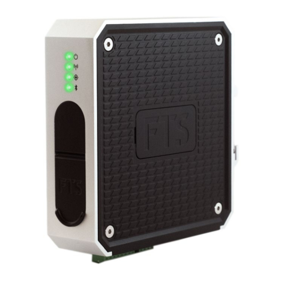
Page 8: Lt1 Parts
LT1 PARTS LED Status Terminal Blocks indicators • Data • Power SIM Card Port Access Port Access (LT1-CELL models) • SD card Telemetry (Cell or Satellite) • Micro-B USB Figure 1-1: Parts of the LT1 COMPLIANCE INFORMATION This device complies with Part 15 of the FCC Rules. Operation is subject to the following two conditions: (1) this device may not cause harmful interference, and (2) this device must accept any interference received, including interference that may cause... -
Page 9: Sdi-12 Version 1.3
Figure 1-2: SD card and Micro-B USB port access The LT1 is shipped with an FTS tested and approved industrial grade SD card inserted in the SD card port. Detailed information on SD cards and their use can be found in section 1.6. -
Page 10: Telemetry And Network Communication
The SIM card holder will be firmly seated in the locked position. To unlock it, gently slide the black holder towards the SIM card holder’s hinge. Once it is unlocked, the SIM card holder will spring up slightly and then it can be swung to its fully open position, from which the SIM card can be removed/inserted. -
Page 11: Lt1-Irid
SD CARDS The LT1 is shipped with an FTS approved industrial grade 4GB SD card inserted in the SD card port and contains the station’s logs. On average, two years data can be stored on this card. This SD card has been tested to work with the LT1’s embedded system and in the environmental conditions in... -
Page 12: Lt1-Cell
1.7.1 LT1-CELL Firmware updates for LT1-CELL units are conducted through FTS360 due to the bi-directional telemetry. In FTS360, select the station and the “Edit Station” button. Select the Update Firmware button and follow the prompts. 1.7.2 LT1-GOES IMPORTANT: Prior to conducting a firmware update on an LT1-GOES ensure you do the following: •... -
Page 13: Lt1-Irid
The LT1-IRID firmware can be updated remotely through FTS360 or on-site. Note that data charges will apply for remote updates. If updating remotely through FTS 360, follow the firmware update instructions for LT1-CELL (section 1.7.1) If updating on-site, follow the firmware update instructions for an LT1-GOES (Section 1.7.2) -
Page 14: Station Management
Two software tools are required to manage LT1 stations: FTS360, a secure web-based software program, and the FTS Config App which must be used for the initial setup and configuration of a station. The FTS Config App can be used with iOS, Android, and Windows 10 devices . -
Page 15: Using Fts360 And The Fts360 Config App
In order for Agency users to have access to FTS360, the Administrator must first initialize the account and assign an Agency name. Note that in some cases, FTS will have completed this step on behalf of the client. If that is the case, the Administrator will not have to Sign Up as outlined in the following paragraph. -
Page 16: Adding Stations
log onto the FTS360 Config App as a member of the Agency to which the station is assigned, • • synchronize with FTS360, and remain logged on (Note: Synchronization occurs automatically when logging onto the FTS360 Config App with an internet connection) Prior to going to the field and immediately upon return (or when internet connection is possible), you should log on to the FTS360 Config App to synchronize with FTS360. -
Page 17: Data Management
SD CARD: All models can also store data locally to the supplied SD card for redundancy. This SD card has been tested to work in the environmental conditions in which the LT1 is designed to operate. Replacing it with a non-FTS approved, standard SD card can cause reduced or lost data in the logs. -
Page 18: Copying Data From The Sd Card
Table 2-2: Data Log Directory and Naming Structure DIRECTORY AND NAMING STRUCTURE DATA LOG TYPE Directory: .csv /LT1-CELL<serial number>/DATA/<filename> /LT1-GOES<serial number>/DATA/<filename> /LT1-IRID<serial number>/DATA/<filename> Naming structure: (8_dig_serial_number)_(8_dig_sequence_number)_(compact_timestamp)_DATA.csv Directory: Raw telemetry /LT1-CELL<serial number>/TELEM/<filename> /LT1-GOES<serial number>/TELEM/<filename>/ LT1-IRID<serial number>/TELEM/<filename> Naming structure: (8_dig_serial_number)_(8_dig_sequence_number)_(compact_timestamp)_TELEM.txt Naming structure example Telemetry log: 00000019_00000160_20180218T062746Z_Telem.txt Sequence LT1 Serial... - Page 19 3) Select the desired files and drag and drop them into a compatible program such as an Excel spreadsheet or Notepad++; 4) Safely eject the SD card from the device and replace it in the LT1; 5) Refresh the dashboard to detect the SD card and display SD card information. 700- LT1-Man Rev 8 09 Feb 2021...
-
Page 20: Station Functionallity While Connected To The App
In order to communicate directly with a station you must: Have access to FTS 360 and be assigned either an Administrator or Technician role • Have downloaded the FTS360 Config App onto the smart device which will be used •... -
Page 21: Using The App With An Android Device
Create and use a checklist of all tools and equipment that will be required on-site SYNCHRONIZING THE APPLICATION Synchronizing the FTS Config App with FTS360 ensures that both programs will have the most current station configuration information. This is extremely important if you will be working offline (ie: no internet connectivity) in the field. -
Page 22: Working Online
Although the FTS360 Config App will periodically synchronize with FTS360 when a network connection is available, a manual synchronization should always be done immediately prior to leaving for the field and immediately upon return. If using an Android device, if the device’s unlock PIN is changed, you must re-log into the FTS360 Config App and synchronize. -
Page 23: Working Offline
If the smart device used to set up a new station is lost or broken before synchronization with FTS360 took place, the station will need to be returned to FTS to be factory reset. Contact FTS Support for direction. -
Page 24: Station Dashboard Elements
dditional Menu items The BLE icon indicates the strength of the signal: Strong signal. Weak signal. Reduce distance to the station. Figure 4-1: Station Discovery Screen To display the station’s dashboard, select Connect. The BLE Status light on the LT1 will become solid “On”... -
Page 25: Additional Menu Items
FCA version • 3.9.2 SWITCH ENVIRONMENTS This is for the exclusive use of FTS Technicians and Service personnel. Customers cannot access this feature. 3.9.3 CLEAR APP DATA Clearing app data should not normally be required. It is a troubleshooting tool used if you believe the app data on your device has been corrupted. -
Page 26: Station Information And Health Icons
3.9.4 STATION INFORMATION AND HEALTH ICONS INDICATOR ICON MEANING/COMMENTS GPS Fix not established. GPS: GPS fix established. Followed by latitude, longitude and elevation. No signal detected. Check antenna. Cellular: Online. Strong signal (RSSI> -69) (LT1-CELL Online. Poor signal (RSSI≥ -69) units only) Extremely weak signal (RSSI≤... -
Page 27: Sensor Information Icons
3.9.5 SENSOR INFORMATION ICONS ICON MEANING/COMMENTS For NMEA or Rain sensor: The named sensor is inactive. The named sensor has not been added or configured. For SDI-12 sensors: Once the named sensor has been added, this icon with the message” Waiting for sensor data”... -
Page 28: Action Buttons
3.9.6 ACTION BUTTONS Add Sensor: Select this to add an SDI-12 sensor (see Chapter 6 for details). Follow prompts on successive screens and complete fields with desired sensor type/details. Refresh: This will refresh the Station identification and health portion of the dashboard. SDI-12 Transparent Mode: Provides capability to send SDI-12 commands to SDI-12 sensors (see section 8.3 for details). -
Page 29: Components
SMA male to N female adaptor antenna • GPS antenna* GPS-ANTENNA-WP OPTIONAL: SIM card (inserted) with *LT1-GOES-GPS-BNDL only purchase of FTS cellular plan LT1-IRID ITEM PART # LT1-IRID complete with: • 4 pin power terminal block LT1-4PIN • 8 pin data terminal block LT1-8PIN •... -
Page 30: General
PW and HT pins. Details of connecting an FT7X2 RS-485 wind sensor are found in App Note 162 (700-AN-162) and posted to the FTS Support site. If using a heated sensor, the associated draw on the supplied power must be taken into account to calculate battery longevity and solar panel requirements. -
Page 31: Power Terminal Block Wiring Diagram
POWER TERMINAL BLOCK WIRING DIAGRAM Power connections to the LT1 are made using the 4 pin power terminal block. Once all connections are made, the terminal block will be inserted into the terminal port to complete the cycle. Chassis Ground Power Ground High Current Power In (for use with FT742 heated anemometer) -
Page 32: Connecting Cellular Telemetry
The LT1-Cell has a dual GPS and cellular antenna each with individual SMA connectors. Mount the dual antenna in the desired position. If mounted inside an enclosure, ensure the materials will not interfere with the GPS’ signal. The FTS enclosure has a built-in antenna mount. Attach the antenna leads to their respective connectors. -
Page 33: Connecting A Tipping Bucket (Rain Guage)
If using the heater option on an attached FT742 RS-485 wind sensor a power source capable of at least 3 A must be attached to both the PW and HT pins. Details of connecting an FT7X2 RS-485 wind sensor are found on the FTS Support Site (App Note 162). MOUNTING THE LT1 •... -
Page 34: Prior To Going To The Field
5.2.1 TESTING THE LT1-CELL If the LT1-CELL unit was purchased with an FTS data plan, it will be shipped with an activated SIM card. If your company did not purchase an FTS data plan, the SIM card from your agency’s cellular plan must be activated and used to test the LT1-CELL. -
Page 35: Testing The Lt1-Goes
The APN is provided by either FTS or your cellular provider, dependant on your agency’s communication plan. See Section 5.3 for a list of APNs for FTS plans and instructions on how to enter the APN if required. - Page 36 If you are unable to complete a full test transmission as noted above, or if you are confident your transmission will not exceed the allotted transmission window, there is no need to configure sensors, just send a “Test GOES Transmission”. NOTE: A “Test GOES Transmission”...
-
Page 37: Testing The Lt1-Irid
Registration line should indicate “Network registration success”. 4) If configuring sensors, connect and configure sensors (Chapter 4). Synchronize the device with FTS 360, disconnect from the station, and confirm the sensor data is published in FTS360 as scheduled. EDDN, for example. -
Page 38: Cellular Telemetry - Entering The Apn
If the station supports cellular telemetry, there are options to configure the cellular mode for customers who have not purchased an FTS cellular plan and need to set up their SIM card. Typically, these settings are automatically sent to the station via the inserted SIM; however, if your provider requires this information to be input manually, do so in this screen. -
Page 39: Station Goes Settings
5.4.1 STATION GOES SETTINGS Unconfigured Settings Configured Settings – Changes Saved NOTE: the information shown in the fields is for demonstration purposes only. You must use the settings provided to you by NOAA/EUMETSAT Figure 5-1 First Transmission Time: This should be minutes and seconds assigned for your transmission time. -
Page 40: Configure Message Transmission
Telem folder (see Section 2.3.2). If the failsafe continues to trip, the unit should be returned to FTS for repair or replacement. Antenna (true north): The antenna’s inclination and bearing information in degrees True. Save Changes: Once all the required fields are filled in, the Save Changes bar will be available. - Page 41 2) Use the drop-down menus to select the message type (Pseudo Binary-USGS, SHEF, or BLM) 3) Input number of redundant messages (optional – not supported by BLM messages). About Redundant Messages: The content of messages can be configured to be repeated in subsequent transmissions.
-
Page 42: Setting Up Random Transmissions
8) Confirm message format: Confirm message format and data points by viewing an example of a configured message. Select Show Configured Message. Note that no data is sent and only simulated values of 1.0 are displayed to illustrate the message format. Reset: If changes have been made but not saved, selecting Reset will discard those changes and remain on the same page. -
Page 43: Creating Alert Conditions
A scheduled message will always be transmitted in accordance with the programmed • schedule. If there is a conflict, Random transmissions will be sent immediately after the scheduled transmission. • Random transmissions have a maximum message size of 77 bytes. Data which exceeds this limit will be truncated. -
Page 44: Test Goes Transmission
5.4.5 TEST GOES TRANSMISSION The test transmission is sent to the LRGS and is used to confirm correct satellite network and antenna power settings. It will not transmit data. To send a test transmission, select the “Test GOES Transmission” button. If you were a assigned a test transmission channel, enter that. If not, select the appropriate channel for your satellite assignation. -
Page 45: Sensor Templates And The Library
CONFIGURING SENSORS Once connected to the LT1 and powered, use the FTS360 Config App to add and configure the sensor(s) for the station. Ensure you test each sensor and save the settings before exiting the page. Upon completion, ensure you synch your changes with FTS360. When determining the sample schedule, bear in mind the time it takes for the sensor to take and register a sample and for that information to be buffered prior to the scheduled transmission. -
Page 46: Lt1-Cell: Calculating Start Time For Sdi-12 And Counter Sensors
LT1-CELL: CALCULATING START TIME FOR SDI-12 AND COUNTER SENSORS This is optional and used for those agencies with a requirement for data readings as close as possible before transmission. If you do not require this level of timing, you can leave the start time at the default setting or set it to the desired minute from which you want the sample readings started. -
Page 47: Configuring An Sdi-12 Sensor
CONFIGURING AN SDI-12 SENSOR 1) Select the Add Sensor bar and select the desired sensor from the drop-down list. HINT: Custom library items created by your agency are listed first, followed by default library items. 2) Edit fields as necessary. 3) Test the sensor(s): Select the Test Sensor bar. -
Page 48: Transparent Mode - Sdi-12 Sensors
6.3.1 TRANSPARENT MODE – SDI-12 SENSORS Select the SDI-12 Transparent Mode button on the Station Dashboard screen to communicate with SDI-12 sensors using SDI-12 commands. You must know the SDI-12 sensor’s address (as entered on the Sensor’s configuration page or by using the address query command - see section 6.3.3.1) and refer to the sensor’s manual for details of SDI-12 commands specific to that sensor. -
Page 49: Configuring A Counter Sensor (Tipping Bucket)
If two SDI-12 sensors are connected to the LT1, there will be two responses returned, one for each address. In order to determine the sensor which corresponds to each address, review each sensor’s configuration page or remove one sensor and re-send the address query command. If there is an address conflict (both sensors have the same address), one sensor will have to be removed and the change address command sent to the connected sensor. -
Page 50: Configuring An Nmea Sensor
CONFIGURING AN NMEA SENSOR Select the NMEA line from the Station Dashboard 1) Select the sensor type from the drop- down menu 2) Fill in the Friendly Name. This is the name that will be displayed in FTS360 and the app 3) Select the desired sample schedule 4) Test the sensor to confirm operation 6 Save Settings... -
Page 51: Start Up
Appendix A LT1 LED STATUS INDICATORS Once power is supplied the LT1 will boot up, connect to the telemetry network, and establish a GPS fix. There are four green LED lights which indicate the status of the system in either of its two modes (operating and low power). -
Page 52: Led Fault Indications
LED FAULT INDICATIONS LED Status Indicators: = On = Off N/A –not applicable (can be on, off, or blinking) Blinking once every 10 seconds = Blinking every second Normal Operation: Comment Indicates This is the state when power is first applied once all System OK connections are made or when initially connecting to the ... - Page 53 Fault attempting to 2) If no BLE status light after trying (1), contact FTS connect Support You are signed 1) If you belong to more than one agency switch to the into the wrong correct agency.
-
Page 54: Lt1 Cell
SDI-12, power, and RS-485 I/O ports are lightning/static protected. Power is reverse polarity protected. SDI-12 and RS-485 ports are short circuit protected. Internal temperature sensor. Based on FTS Cellular Logger/Transceiver Specifications dated Feb 2020 700- LT1-Man Rev 8 09 Feb 2021 Page 48/60... -
Page 55: Lt1-Goes
135mm x 135mm x 40 mm (5.3” x 5.3” x 1.6”) Weight 682g (1.5 lb) Material 6000 Aluminum (C-spine) ABS/PC (clamshell) TPE plastic (SD card door) Housing Rating IP51 Based on FTS Logger/Transceiver Specifications dated May 7, 2018 700- LT1-Man Rev 8 09 Feb 2021 Page 49/60... - Page 56 PHYSICAL (continued) Connectors 4 pin terminal strip (mates with Phoenix Contact 1840382) 8 pin terminal strip (mates with Phoenix Contact 1840421) Connectors compatible with wires 16 to 28 AWG. GPS and Satcom (SMA female/jack ports) USB micro-B port Communication Ports One SDI-12 Port (accessible via 8 pin terminal strip) One RS-485 Port (receive only, accessible via 8 pin terminal strip) One GPS Port (receive only, accessible via SMA port)
-
Page 57: Lt1-Irid
LT1-IRID PERFORMANCE DATA Local Access BLE enabled iOS or Android platform. Remote Access Using FTS360 software Local Data Storage Up to 2 years ENVIRONMENTAL Operating Temperature -40°C to +70°C (-40°F to +158°F) Storage Temperature -40°C to +70°C (-67°F to +158°F) Relative Humidity 0-95% non-condensing PHYSICAL... -
Page 58: And 8 Pin Connector Maximum Ratings
DATA and TRANSMISSION Data Rates Satcom (Iridium): 340 B (Max Mobile Originated Message Size 270 B (Max Mobile Terminated Message Size) Satcom (Iridium): 1616 to 1626.5 MHz Transmit Frequency Bluetooth: 2360 to 2500 MHz Ranges RF Bandwidths Satcom (Iridium): 31.5 kHz Bluetooth: 1 MHz RF Transmit Power Satcom (Iridium): +32 dBm max. -
Page 59: Power Output Pin Specifications
POWER OUTPUT PIN SPECIFICATIONS 8-pin connector Name Pin Function Specification pin # SDI-12 Power Out Output: Internally connected to 4 pin connector PW 750 mA max. current draw RS-485 Sensor Power Output: Before using, strap 4 pin connector PW pin to HT pin (see 700-AN-162) Internally connected to 4 pin connector PW 2 A max. - Page 60 Product: Logging Transceiver Model/type: LT1-CELL Manufacturer FTS (Forest Technology Systems) Address 1065 Henry Eng Place, Victoria, BC V9B 6B2, Canada This declaration is issued under the sole responsibility of the manufacturer. The object of the declaration described above is in conformity with the relevant Union...
- Page 61 700- LT1-Man Rev 8 09 Feb 2021 Page 55/60...
-
Page 62: Certifications - Lt1-Cell And Lt1-Cell-Vz
Appendix D CERTIFICATIONS AND REGULATORY NOTICES CERTIFICATIONS - LT1-CELL AND LT1-CELL-VZ FCC Certification: CFR Title 47 FCC Part 15 Subpart B – Unintentional radiators (LT1-CELL/LT1-CELL-VZ) CFR Title 47 FCC Part 15 Subpart C – Intentional radiators IC Certification: ICES-003 (LT1-CELL/LT1-CELL-VZ) CE Certifications: Directive 1999/5/EC –... -
Page 63: Certifications - Lt1-Goes
CERTIFICATIONS - LT1-GOES FCC Certification: CFR Title 47 FCC Part 15 Subpart B – Unintentional radiators IC Certification: ICES-003 Issue 6 CE Certifications: Directive 1999/5/EC – Radio and telecommunications terminal equipment (RTTE) Directive 2011/65/EU – RoHS directive (RoHS NESDIS Certification NOAA NESDIS GOES Data Collection Platform Radio Set (DCPRS) Certification Standards at 300bps and 1200bps, Version 2.0, June 2009 and CGMS International Standard, Version 1, 2009... -
Page 64: Fcc Part 15 Regulatory Notices
Increase the separation between the equipment and the receiver • Modification Statement: FTS has not approved any changes or modifications to this device by the user. Any changes or modifications could void the user’s authority to operate this equipment and/or obtain warranty service for this equipment. - Page 65 RF EXPOSURE This equipment complies with FCC and IC radiation exposure limits for an uncontrolled environment. The antenna should be installed and operated with a minimum of 20 cm between the radiator and your body. Cet appareil est conforme aux limites d'exposition aux rayonnements de la FCC et la IC pour un environnement non contrôlé.
- Page 66 DOCUMENT REVISION HISTORY Revision Date Description 12 Apr 2017 Original release Updated to include LT1-CELL-SYSTEM set up, updated LED 05 Jun 2017 status, new conformities and certifications (Peru, Columbia) Added time limit for synchronization 20 Nov 2017 Updated for LT1 FW v1.4.7 and FTS360 Config App v1.3.04. 8 May 2018 Added LT1-GOES, FTS360 Config App info, added more troubleshooting...
Need help?
Do you have a question about the T1-CELL and is the answer not in the manual?
Questions and answers