Advertisement
(1)
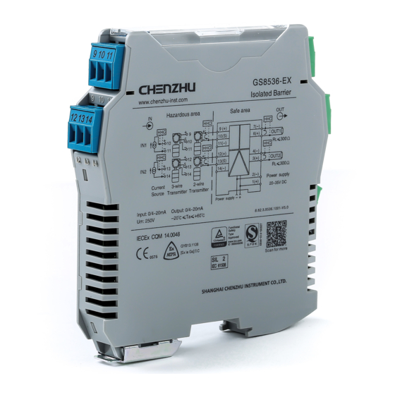
. This barrier adopts knock-down connector with screw terminals. The
intrinsically safe(IS for short) terminals (blue plugs) should be connected
to hazardous area devices and the non-IS ones (green plugs)to the safe
area devices.
(2).
Choose for the harzardous area the blue-marked wires. Its minimum
2
cross section area should be 0.5 mm ,and minimum dielectric strength
should be 500V.
(3).
The wirings in safe area and hazardous area must be separated,
and both have protection bushes.
(4).
A length of 8mm bared wire is locked by the M3 bolt. See as shown
below.
Non-intrinsically safe terminals
Intrinsically safe terminals
8.0
M3
The isolated barrier should be located at safe area, according to the
related requirements in IEC60079-14(EN60079-14),IEC60079-
17(EN60079-17),IEC60079-19(EN60079-19),IEC60079-25(EN60079-
25),GB15577,GB12476 and GB50257.
GS8500-EX series isolated barrier are designed for mounting on
35mm DIN guide rail.
Installation according to the following steps:
(1). First make the bus-powered outlet locked into the guide rail;(If no
bus-powered function,omit this step);
(2). Make the upside of the barrier locked into the guide rail;
(3). Push the downside of the barrier in the rail.
2
1
3
4
(1).Insert a screwdriver (its edge length≤ 6mm)into the downside metal
lock of the barrier;
(2).Push the screwdriver upwards,then prize the metal lock downwards;
(3).Take the barrier out of the guide rail.
1
2
(1).Before using, please check again whether the module's Ex-proof
rating accords to the operation conditions, and also wiring and polarity
are correct.
(2).It is disallowable to test insulativity among the terminals with a
megameter. If necessary, the wires must be cut off before testing ,or the
internal fuse would blow.
(3).Every product has been test strictly before leaving factory. If users
find any abnormality in the module, please contact the nearest agent or
our company.
(4).In 5 yeras from the delivery date, if the product works improperly
during normal operation, we will repair or replace it without payment.
Add: Building 6, 201 Minyi Road, Caohejing Hi-Tech Park
Songjiang New Industrial Park, Shanghai 201612, P.R. China
Tel : +86-21-64513350 Fax : +86-21-64846984
Email:chenzhu@chenzhu-inst.com
http://www.chenzhu-inst.com
5
3
Please read the instruction manual carefully before use the product,
and please safekeeping.
Please check whether the product type on the package accords
to the ordering contract;
Read this manual carefully before installation or using. If there is
something unclear, please dial technic support hotline-400 881 0780;
Isolated barrier should be located in the safe area;
Supply voltage is 24VDC, 220VAC is forbidden;
Users are not allowed to dismantle or repair the barrier otherwise
it will induce malfunction.
CZ.GS8536-EX.11(S)E-5.1/18.01
GS8536-EX
GYB18.1155
IECEx CQM14.0048
YEAR
YEAR
WARRANTY
WARRANTY
Caution
Advertisement
Table of Contents

Related Manuals for Chenzhu GS8536-EX


Summary of Contents for Chenzhu GS8536-EX
- Page 1 (2). Choose for the harzardous area the blue-marked wires. Its minimum cross section area should be 0.5 mm ,and minimum dielectric strength GS8536-EX should be 500V. (3). The wirings in safe area and hazardous area must be separated, and both have protection bushes.
- Page 2 (such as big current or spark,etc.)must be source signal)) which generated by the transmitter form hazardous area avoided when using. GS8536-EX to safe area separately, also allows bi–directional transmission of HART (2). Operating temperature: -20℃~+60℃ communication signals. The product needs an independent power supply.
Need help?
Do you have a question about the GS8536-EX and is the answer not in the manual?
Questions and answers