Advertisement
Quick Links
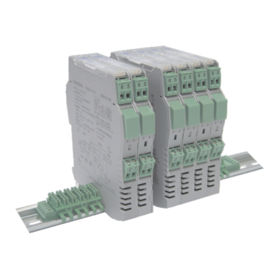
Connections
(1)
This barrier adopts a pluggable connector with screw terminals.
The intrinsically safe(IS) terminals (blue plugs) should be connected
to hazardous area devices and the non-IS ones (green plugs) to the
safe area devices.
(2)
Choose for the hazardous area the blue-marked wires. Its
minimum cross-section area should be 0.5mm , and the minimum
dielectric strength should be 500V.
(3)
The wirings in the safe area and the hazardous area must be
separated, and both have protection bushes.
(4)
A length of 7mm bared wire is locked by the M3 bolt. See as shown
below.
Non-intrinsically safe terminals
Intrinsically safe terminals
7.0
M3
Installation
The isolated barrier should be installed in the safe area, according
to the related requirements in
GB 3836.13-2013, GB/T 3836.15-2017,
GB/T 3836.16-2017, GB/T 3836.18-2017, GB 15577-2018 and GB 50257-
2014.
The isolated barrier is designed for mounting on 35mm DIN rail.
Installation procedure:
(1) Clamp the bus connector on the rail;
(If no bus-powered function, omit this step);
(2) Hook the backplane of the barrier into the top of the rail;
(3) Press downward.
2
1
3
4
Disassembly
(1) Insert a screwdriver (its edge length≤ 6mm)into the downside
metal lock of the barrier;
(2) Push the screwdriver upwards, then prize the metal lock
downwards;
(3) Take the barrier out of the rail.
2
Maintenance
(1) Before using, please check again whether the product's model and
Ex-proof rating are consistent with the operation conditions; whether
the wiring and polarity are correct.
(2) It is disallowable to test the insulation among the terminals with a
megameter. The wiring must be disconnected before testing the
insulation of the system, otherwise the internal fuse would blow.
(3) Every product has been strictly tested before leaving factory. If
product does not work properly, please contact the nearest agent or
technic support hotline.
(4) In 5 years from the delivery date, if the product works improperly
during normal operation, we will repair or replace it without payment.
Add: Building 6, 201 Minyi Road, Caohejing Hi-Tech Park
Songjiang New Industrial Park, Shanghai 201612, P.R. China
Tel : +86-21-64513350 Fax : +86-21-64846984
Email: chenzhu@chenzhu-inst.com
http://www.chenzhu-inst.com
3
1
2
5
User Manual
Isolated Barrier
GS8512-EX.12
GYB20.1589
Please read the user manual carefully before using the product, and
please keep it properly for further reference.
Caution
Please check whether the product type on the package accords to the
ordering contract;
Read this manual carefully before installation or use. If there is something
unclear, please contact technical support;
Isolated barrier should be installed in the safe area;
Supply voltage is 24VDC, 220VAC is forbidden;
It is strictly forbidden to disassemble the barrier to prevent from failing
or malfunction.
CZ.GS8512-EX.12.11(S)E-6.0/20.01
YEAR
YEAR
WARRANTY
WARRANTY
Advertisement

Subscribe to Our Youtube Channel
Related Manuals for Chenzhu GS8512-EX.12


Summary of Contents for Chenzhu GS8512-EX.12
- Page 1 Choose for the hazardous area the blue-marked wires. Its (3) Take the barrier out of the rail. minimum cross-section area should be 0.5mm , and the minimum GS8512-EX.12 dielectric strength should be 500V. The wirings in the safe area and the hazardous area must be separated, and both have protection bushes.
- Page 2 The output can be provided to select phase reversal and to enable the nickel and silver. Moreover, please avoid using this product in violent GS8512-EX.12 line fault detection. The product needs an independent power supply quiver,impact or strong electromagnetic interference environment.
Need help?
Do you have a question about the GS8512-EX.12 and is the answer not in the manual?
Questions and answers