Chapters
Table of Contents

Related Manuals for FARMALABOR OPTIMATIC 300

Summary of Contents for FARMALABOR OPTIMATIC 300
- Page 1 Opercolatrice semi automatica / Semi- automatic capsule filling machine OPTIMATIC 300® Manuale d’uso e manutenzione / Use and maintenance manual Version 1 - 2018- Italiano/ English...
- Page 2 ITALIANO...
-
Page 3: Table Of Contents
ITALIANO SOMMARI O Introduzione ............................4 Utilizzo del manuale ......................4 1.1.1 Simbologia e terminologia utilizzata nel manuale ............4 Garanzia del costruttore ...................... 5 Decadenza della garanzia ..................... 5 Campo di applicazione ......................... 5 Le polveri: come classificarle....................6 Le polveri: come maneggiarle .................... - Page 4 ITALIANO 5.7.1 Smontaggio/Montaggio ....................24 5.7.2 Accorgimenti per la pulizia ................... 29 Messa fuori servizio ......................29 Spedizione e trasporto ....................... 29 Rottamazione e smaltimento ......................29 Schema elettrico ..........................30 Risoluzione problemi .......................... 31 Elenco delle norme legislative e tecniche adottate ................31...
-
Page 5: Introduzione
Prima dell’utilizzo leggere attentamente il presente manuale di istruzioni. La garanzia di buon funzionamento dell’attrezzatura è strettamente dipendente dalla corretta applicazione di tutte le istruzioni contenute nel manuale. In caso di smarrimento del manuale contattare la Farmalabor SRL. 1.1.1 SIMBOL OGIA E TERMINO LOGIA UTILIZZATA NE L MANUALE... -
Page 6: Garanzia Del Costruttore
Tutti i prodotti vengono accuratamente controllati, collaudati prima della spedizione e sono garantiti dalla società Farmalabor s.r.l. per il periodo di 12 (dodici) mesi dalla data di consegna, salvo il naturale consumo delle parti soggette ad usura. La garanzia non comprende i costi per le prestazioni di manodopera e si riferisce esclusivamente alle parti che si riscontrassero difettose per motivi accertati, imputabili al costruttore per difetto di costruzione o qualità... -
Page 7: Le Polveri: Come Classificarle
Essiccanti, assorbono l’umidità nel preparato che potrebbe danneggiare il principio attivo oltre a diminuire la scorrevolezza delle polveri (es. silice colloidale, caolino, etc.). La Farmalabor produce alcune miscele di eccipiente-base, già pronte per l’utilizzo, costituite da diluenti, lubrificanti ed essiccanti. - Page 8 ITALIANO CAPSULE Tipo Capsula Capacità (volume) Capacità peso Dimensioni (densità= 1gr/ml) (lunghezza) 000 (triplo zero) 1,35 ml 1350 mg 2,61 cm 00 (doppio zero) 0,95 ml 950 mg 2,33 cm 0 (zero) 0,70 ml 700 mg 2,12 cm 1 (uno) 0,50 ml 500 mg 1,90 cm...
-
Page 9: Descrizione Generale
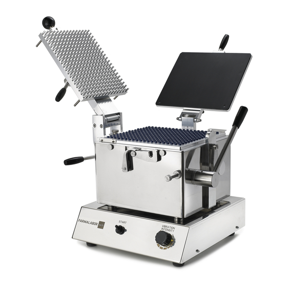
270 e 330 milligrammi. DESCRIZIONE GENERALE La Opercolatrice Semiautomatica Optimatic 300 è composta dal gruppo opercolatrice montato su un basamento nel quale è installato il supporto vibrante. Come altre macchine costruite dalla Farmalabor Tech, la opercolatrice semiautomatica Optimatic 300 può... -
Page 10: Generalità
ITALIANO Inoltre un vibratore elettromagnetico assicura una distribuzione uniforme delle sostanze all’interno delle capsule. GENERALITÀ L’opercolatrice semiautomatica è composta dai seguenti componenti principali, Figura 1: Figura 1: Componenti principali Unità vibrante; Gruppo opercolatrice; Coperchio di chiusura; Pestello; Set piastre; Convogliatore; Leva blocco capsule;... -
Page 11: Caratteristiche Tecniche
ITALIANO 3.1.1 CARATTERISTICHE TECN ICHE Nome Opercolatrice semiautomatica Modello Optimatic 300 Produzione Oraria Max 8000 capsule in funzione del prodotto Tensione 230 Volt- 50/60 Hz Potenza assorbita 450 W Ingombro massimo (A x B x C) 342 mm x 368 mm x 674 mm... -
Page 12: Contenuto Confezione
Manuale d’uso e manutenzione. Figura 4: Opercolatrice Figura 5: Kit di trasformazione * Componetene da scegliere in funzione del tipo di capsule da utilizzare. 3.1.3 ACCESSORI CAMBIO FORMATO SEMIA UTOMATICA OPTIMATIC 300 Codice Descrizione 015303 Kit trasformazione Optimatic 300 Formato “000” 015304 Kit trasformazione Optimatic 300 Formato “00”... -
Page 13: Identificazione
ITALIANO IDENTIFICAZIONE La marcatura CE apposta sulla parte posteriore del basamento, riporta le principali caratteristiche. Figura 6: Marcatura CE Per una corretta individuazione del dispositivo, e per ottenere la tracciabilità del prodotto, tutti particolari caratteristici delle nostre attrezzature sono marcati, in particolare: ... -
Page 14: Installazione
ITALIANO Sulla piastra centrale è marcato il tipo di capsula che può essere processato; Figura 8: Identificazione piastra centrale Sul pestello è marcato il numero di serie (A) ed il tipo di capsula che può processare (B), Figura 9. Figura 9: Marcatura pestello INSTALLAZIONE CONDIZI ONI AMBIENTAL I... -
Page 15: Posizionamento
ITALIANO POSIZIONAMENT O Per il posizionamento dell’attrezzatura prevedere una spazio minimo di 100 cm x 100 cm necessari per facilitare sia la normale attività che gli interventi di regolazione e manutenzione. Liberata la macchina dal suo imballo, trasferirla con la massima cura su di un banco avente dimensioni minime di 40 cm x 40 cm, in grado di sostenere un peso almeno di 100 kg. -
Page 16: Regolazione Altezza Capsule
ITALIANO 5.2.1 REGOLA ZIONE A LTEZZA CAPSULE Ogni qualvolta che si cambia la tipologia del prodotto da processare occorre regolare l’altezza del corpo delle capsule rispetto al livello della piastra di base (C), che deve essere sempre al pari, o di 0,2 mm più basso. Questa regolazione si effettua agendo sul dado (A) e sulla vite (B) posti sul fronte della macchina, Figura 11. -
Page 17: Regolazione Coperchio Di Chiusura
ITALIANO 5.2.3 REGOLA ZIONE C OPERCHI O DI CHIUSURA Abbassare il coperchio di chiusura A, Figura 14; Figura 14: Coperchio di chiusura abbassato Sbloccare le ghiere di fermo (B) e agire con la chiave a brugola sui grani (C) (Chiave a brugola numero N°6), Figura 15 e Figura 16;... -
Page 18: Impiego Del Convogliatore
ITALIANO Figura 17: Gancio di chiusura A regolazione avvenuta, serrare le ghiere di fermo (B), Figura 17. IMPIEGO DEL CONV OGLI ATORE Versare alla rinfusa sul convogliatore una quantità di capsule superiore alla capacità del convogliatore stesso. Schermare con una mano il lato libero, scuotere ed inclinare leggermente il convogliare con un movimento ondulatorio, per permettere alle capsule di disporsi negli alloggiamenti. - Page 19 ITALIANO Posizionare Il convogliatore sulla opercolatrice, Figura 19; Figura 19: Posizionamento convogliatore Per posizionare il convogliatore sull’opercolatrice, fare in modo che i piedini di guida (D) del convogliatore risultino inseriti in una delle tre coppie di fori di centraggio (E), ricavati nella parte superiore della piastra base dell’opercolatrice, Figura 20.
-
Page 20: Impiego Dell'opercolatrice
ITALIANO Figura 21: Orientamento capsule Figura 22: Capsule orientate Dopo essersi assicurati che tutte le capsule sono alloggiate nei rispettivi alveoli, rimuovere il convogliatore sfilandolo verso l’alto. Ripetere le medesime operazioni, posizionando il convogliatore sulle altre due coppie di fori di centraggio (2) e (3), Figura 20. - Page 21 ITALIANO Bloccare i corpi delle capsule facendo pressione sulla leva (G), Figura 24; Figura 24: Blocco corpo capsule Aprire le capsule esercitando una pressione sulla leva (H) posta sul lato destro della macchina, Figura 25; Riportare la leva (G) in posizione di partenza. Questa operazione consente di separare il corpo delle capsule dalle teste le quali restano imprigionate sulla piastra base.
- Page 22 ITALIANO Figura 26: Inserimento cornice di dosaggio Versare sul piano dell’opercolatrice il prodotto necessario al riempimento delle capsule. Distribuire il prodotto con l’aiuto della spatola (M), Figura 27. La cornice di dosaggio, posizionata sul piano, evita le dispersioni di materiale permettendo la raccolta del materiale in accesso sula parte frontale della cornice (O).
- Page 23 ITALIANO Figura 29: Attivazione unità vibrante Abbassare la piastra pestello (R) e bloccarla mediante il gancio (S), Figura 30 e Figura 31. Figura 31: Gancio di blocco Figura 30: Piastra pestello Agire sul volantino (T) per comprimere le polveri nel corpo delle capsule. Ad operazione ultimata portare il volantino nella posizione iniziale, Figura 32.
-
Page 24: Chiusura Capsula
L’attrezzatura deve essere utilizzata rispettando le indicazioni contenute nel Manuale d’istruzioni; un impiego diverso da quello previsto, può recare danno alla macchina e costituire pericolo per le persone o cose in genere. La FARMALABOR S.R.L. declina ogni responsabilità per un uso non corretto dell’attrezzatura. -
Page 25: Manutenzione E Riparazione
ITALIANO MANUTENZIONE E RIPAR AZIONE La macchina deve essere sottoposta a verifica e manutenzione periodica per mantenere inalterate, nel tempo, la funzionalità, le condizioni di igiene e sicurezza. 5.7.1 SMONTAGGIO/ MONTAGGIO L’unità vibrante e il gruppo opercolatrice sono facilmente separabili, consentendo la completa pulizia di entrambi. - Page 26 ITALIANO Figura 35: Smontaggio leva di blocco capsule La leva è composta da un pomello zigrinato (E), una rondella piana (F), una boccola (G) e un perno eccentrico (H), Figura 36; Figura 36: Composizione leva di blocco capsule...
- Page 27 ITALIANO Svitare i 4 pomelli zigrinati (I) che fissano il ricambio (2 fronte e 2 retro), Figura 37; Figura 37: Smontaggio piastra di ricambio Estrarre il set piastre dalla sua sede, Figura 38; Figura 38: Estrazione set piastre...
- Page 28 ITALIANO Estrarre la piastra base, Figura 39; Figura 39: Estrazione piastra base Estrarre il supporto con il gancio, Figura 40; Figura 40: Estrazione supporto con gancio...
- Page 29 ITALIANO Per un accurata pulizia del set piastre sfilare la linguetta interna, Figura 41; Figura 41: Pulizia set piastre Sfilare il supporto con il gancio in modo tale da avere la struttura libera per la pulizia dei componenti interni, Figura 42; Figura 42: Pulizia interna Per scollegare l’unità...
-
Page 30: Accorgimenti Per La Pulizia
ITALIANO 5.7.2 ACCORGIMENTI PER LA PULIZIA Pulire settimanalmente o dopo ogni utilizzo, con un panno umido e con opportuni detersivi neutri. Asciugare con cura, adoperando un panno morbido. Non bagnare i componenti elettronici. MESSA FUORI SERVI ZIO In caso di non utilizzo per un lungo periodo è necessario effettuare una accurata pulizia dell’attrezzatura e in seguito proteggerla opportunamente, affinché... -
Page 31: Schema Elettrico
ITALIANO SCHEMA ELETTRICO Denominazione Descrizione F1 – F2 Fusibili da pannello Interruttore generale HL-BL Led interruttore blu Modulo variatore di potenza Elettomagnete Elemento ferritico... -
Page 32: Risoluzione Problemi
ITALIANO RISOLUZIONE PROBLEMI Guasto riscontrato Cause Risoluzione Collegare il dispositivo alla Il dispositivo non si Il dispositivo non è linea di alimentazione; accende collegato alla linea di Controllare linea alimentazione; alimentazione. Ci sono problemi con la linea di alimentazione. Pulire piastre Il set piastre non Tra le due piastre è... - Page 34 ENGLISH...
- Page 35 ENGLISH SUMMARY Introduction ............................4 Use of handbook ........................4 1.1.1 Symbology and terminology used in the use and maintenace manual ......4 Statement and guaranty of THE of the manufacturer ............5 Warrenty loss ........................5 Field of application ..........................5 Powders: how to classify ......................
- Page 36 ENGLISH 5.7.1 Assembly/disassembly ....................24 5.7.2 Cleaning suggestions ....................29 Long time inactivity ......................29 Shipment ..........................29 Scrapping and material disposal ......................29 Electrical wiring diagram ........................30 Problem resolution..........................31 List of applying legal abd technical specifiction .................. 31...
-
Page 37: Introduction
The manual must be kept in a suitable place. In case of loss or deterioration, the replacement documentation must be requested directly from FARMALABOR S.R.L. Before using your filling system please read this handbook carefully. The right functioning of your equipment depends on the right application of the instructions in this handbook. -
Page 38: Statement And Guaranty Of The Of The Manufacturer
Farmalabor s.r.l. or the authorized dealer who made the sale is bound to provide labour for warranty repair, the cost of which will be at the expense of the purchaser. -
Page 39: Powders: How To Classify
Desiccants: they absorb humidity in the preparation that could damage the active ingredient besides reducing fluency of the powders: (es. silica gel, clay, etc.). Farmalabor produces excipient - base mixtures, which are ready for use and made of diluents, lubricants and desiccants. - Page 40 ENGLISH Mix again; Proceed to fill the capsules. (*) After measuring the volume taken by the active ingredient (point 2), choose the capsule using the following tables: CAPSULE Capsule size Capacity (volume) Weight capacity Dimension (length) (density= 1 gr/ml) 1,35 ml 1350 mg 2,61 cm...
-
Page 41: General Description
GENERAL DESCRIPTION The Optimatic 300 Semi-automatic capsule filling machine consists of a capsule filling unit mounted on a base in which the vibrating support is installed. Like other machines manufactured by Farmalabor Tech, the Optimatic 300 semi-automatic capsule filler can process any type of hard gelatine capsules, from the format "000"... -
Page 42: Generalities
ENGLISH GENERALITIES Semi-automatic capsule filler is made of the following main components, Fig 1. Fig 1: Main components Vibrating unit; Capsule filling machine; Closing lid; Pestle; Set plates; Conveyor; Capsule block lever; Capsule opening / closing lever; Capsule body adjustment pin. -
Page 43: Technical Features
ENGLISH 3.1.1 TECHNICAL FEATURES Name Semi-automatic capsule filling machine Model Optimatic 300 Hourly production Max 8000 capsules according to the product Voltage 230 Volt- 50/60 Hz Power supply 450 W Overall size (A x B x C) 342 mm x 368 mm x 674 mm... -
Page 44: Contents Of The Package
Fig. 5: Conveyor kit 3.1.3 ACCESSORIES OPTIMATIC SEMIAUTOMA TIC 300 SIZE CHANGE Code Description 015303 Adjustment kit Optimatic 300 Format “000” 015304 Adjustment kit Optimatic 300 Format “00” 015305 Adjustment kit Optimatic 300 Format “0” 015306 Adjustment kit Optimatic 300 Format “1”... -
Page 45: Identification
ENGLISH IDENTIFICATION The EC marking on the back of the base shows the main features. Fig. 6: EC marking For a correct identification of the device, and to obtain the traceability of the product, all the particular features of our equipment are marked, in particular: ... -
Page 46: Installation Of The Machine
ENGLISH The type of capsule that can be processed is marked on the central plate; Fig. 8: Central plate identification On the pestle the serial number (A) and the type of capsule that can process (B) is marked, Fig. 9. Fig. -
Page 47: Positioning
ENGLISH POSITIONING For the positioning of the equipment, provide a minimum space of 100 cm x 100 cm necessary to facilitate both normal activities and adjustments and maintenance. Once the machine has been freed from its packaging, transfer it carefully bench having a minimum size of 40 cm x 40 cm, capable of supporting a weight of at least 100 kg. -
Page 48: Capsule Height Adjustment
ENGLISH 5.2.1 CAPSULE HEIGHT ADJUS TMENT Whenever the type of product to be processed is changed, the height of the capsule body must be adjusted with respect to the level of the base plate (C), which must always be at least equal, or 0.2 mm lower. This adjustment is carried out by acting on the nut (A) and on the screw (B) on the front of the machine, Fig. -
Page 49: Closing Cover Adjustment
ENGLISH 5.2.3 CLOSING C OVER AD JUST MENT Lower the closing cover (A), Fig. 14; Fig. 14: Closing cover lowered Unlock the lock nuts (B) and use the wrench on the bolts (C) (Allen wrench number N ° 6), Fig. 15 and Fig. -
Page 50: Use Of The Conveyor
ENGLISH Fig. 17: Closing hook Once the adjustment has been made, tighten the lock nuts (B), Fig. 17. USE OF THE CONVEYOR Pour on the conveyor a quantity of capsules higher than the capacity of the conveyor itself. Shield the free side with one hand, shake and slightly incline the conveyor with a wave motion, to allow the capsules to place themselves in the housings. - Page 51 ENGLISH Position the conveyor on the capsule filler, Fig. 19; Fig. 19: Conveyor positioning To position the conveyor on the capsule filler, make sure that the guide pins (D) of the conveyor are inserted in one of the three pairs of central holes (E), obtained in the upper part of the base plate of the capper, Fig.
-
Page 52: Use Of The Capsule Filling
ENGLISH Fig. 21: Orientation capsule Fig. 22: Oriented capsules After making sure that all the capsules are seated in their respective cells, remove the conveyor by pulling it upwards. Repeat the same operations, positioning the conveyor on the other two pairs of central holes (2) and (3). USE OF THE CAPSULE F ILLING Once the conveyor loading procedure has been completed, align the capsules by lowering the closing lid, Fig. - Page 53 ENGLISH Fig. 24: Capsule body block Open the caps by pressing the lever (H) on the right side of the machine, Fig. 25; Return the lever (H) to the starting position. This operation allows to separate the body of the capsules from the heads which remain trapped on the base plate.
- Page 54 ENGLISH Apply the powder recovery frame (L), Fig. 26; Fig. 26: Powder recovery frame insertion Pour the product necessary for filling the capsules on the level of the capper. Distribute the product with the help of the spatula (M), Fig. 27. The dosage frame, positioned on the top, avoids the dispersion of material allowing the collection of the material in access on the front of the frame (O).
- Page 55 ENGLISH To guarantee a homogeneous distribution of the powders, even in the case of poorly powders, the vibrating unit can be activated by means of the switch (P) and adjusting the intensity of the vibration with the potentiometer, Fig. 29; Fig.
-
Page 56: Capsula Closing
The equipment must be used in full compliance with the instructions of this Handbook; any measurement of the machine might damage the system or put in danger persons or things. FARMALABOR S.R.L. declines any responsibility resulting from any wrong use of the equipment. -
Page 57: Maintenance And Reparation
ENGLISH MAINTENANCE AND REPARATI ON The machine must undergo periodical checks and maintenance to maintain functionality, hygiene and safety conditions over time. 5.7.1 ASSEMBLY/DISASSEMBLY The vibrating unit and the capsule filling unit are easily separable, allowing complete cleaning of both. To disconnect the vibrating unit from the capsule filling, perform the following procedure: Unscrew the knob (A) on the left lever, Fig. - Page 58 ENGLISH Remove lever (D) from the seat, Fig. 35; Fig. 35: Disassembly of the capsule locking lever The lever is composed of a knurled knob (E), a flat washer (F), a bush (G) and an eccentric pin (H), Fig. 36. Fig.
- Page 59 ENGLISH Unscrew the 4 knurled knobs (I) that fix the spare part (2 front and 2 back), Fig. 37; Fig. 37: Removing the replacement plate Remove the plate set from its seat, Fig. 38; Fig. 38: Plate set extractor...
- Page 60 ENGLISH Remove the base plate, Fig. 39; Fig. 39: Base plate removal Remove the support with the hook, Fig. 40; Fig. 40: Support with the hook removal...
- Page 61 ENGLISH To carefully clean the plate set, pull out the internal tab, Fig. 41; Fig. 41: Plate set cleaning Extract the support with the hook so as to have the free structure for cleaning the internal components, Fig. 42; Fig. 42: Internal cleaning To disconnect the vibrating unit from the capsule filling, unscrew the four nuts (L) with a socket wrench N °...
-
Page 62: Cleaning Suggestions
ENGLISH 5.7.2 CLEANING SUGGESTIONS Clean weekly or after each use with a damp cloth and appropriate neutral detergents. Dry carefully with a soft cloth. Do not wet the electronic components. LONG TIME INACTIVITY If you do no use the equipment for a long time, you have to keep it cleaned and protected from dust, humidity or any other external element that might damage any of its components. -
Page 63: Electrical Wiring Diagram
ENGLISH ELECTRICAL WIRING DIAGRAM Denomination Description F1 – F2 Panel fuses Main switch HL-BL Led blue switch Power variator module Electromagnet Ferritic element... -
Page 64: Problem Resolution
ENGLISH PROBLEM RESOLUTION Problem Causes Resolution Connect the device to The device doesn’t The device is non property the mains; switch on connected to the mains; Check the supply line; There are problems with the mains line. Clean the two plates The plate set does not Dust is present between the referring to paragraph... - Page 65 Via Oberdan, 52 76012- Canosa di Puglia (Bt) ITALY Dichiara che l’apparecchio OPTIMATIC 300 è conforme alle normative di Sicurezza concernente alle direttive CE per la COMPATIBILITA’ ELETTROMAGNETICA (2014/30/UE) E LA BASSA TENSIONE (2014/35/UE) e alla direttiva macchine (2006/42/CE). Declares that the OPTIMATIC 300 appliance complies with the safety regulations concerning the EC directives for ELECTROMAGNETIC COMPATIBILITY (2014/30 / EU) AND LOW VOLTAGE (2014/35 / EU) and the Machines Directive (2006/42 / EC).
- Page 66 ITALIANO / ENGLISH NOTE- REMARKS...
- Page 68 Stabilimento Sede di rappresentanza La qualità aziendale Via Pozzillo, Zona Industriale Via Palermo, 23 è riconosciuta 76012- Canosa di Puglia (Bt) 20090- Assago (Mi) dalle certificazioni T. +39 0883 611301 info@farmalabor.it ISO 9001:2008 F. +39 0883 664824 www.farmalabor.it ISO 14001:2004...