Table of Contents
Advertisement
Talk to us. We listen.
MicroBox-7824B E-Series Fanless Industrial MicroBox Computer
MicroBox-7824B-E01
MicroBox-7824B-E02
This manual is a user guide for Microbox-7824B E-Series Fanless
Industrial MicroBox Computer. It includes detailed description about how
to install and operate the product. Arista Corporation recommends users to
read through the entire manual and follow instructions to avoid any kind of
obscurity in using the product. For any questions or support, please call us
at 1.877.827.4782 Monday through Friday 8:00am to 5:00PM Pacific Time.
Advertisement
Table of Contents

Related Manuals for Arista MicroBox-7824B-E01


Summary of Contents for Arista MicroBox-7824B-E01
- Page 1 This manual is a user guide for Microbox-7824B E-Series Fanless Industrial MicroBox Computer. It includes detailed description about how to install and operate the product. Arista Corporation recommends users to read through the entire manual and follow instructions to avoid any kind of obscurity in using the product.
-
Page 2: Product Safety Precautions
Product safety precautions Read this document before installation,configuration and operation of this equipment. Users are required to familiarize with all the information and applicable standards prior to using this manual. This manual should be saved for future reference and use. •... -
Page 3: Table Of Contents
Physical dimensions ........................12 Chapter 3 Connections ....................14 Pins in the Serial port( COM1~COM4)..................15 Pins in the VGA port........................16 Pins in the GPIO port (only for MicroBox-7824B-E01)..............17 Pins in the DC-IN power connector....................18 Mounting the MicroBox computer....................19 Connecting to display....................23 Connecting to touch screen....................24 Connecting to keyboard or mouse....................24... -
Page 4: Chapter 1 Welcome
Chapter 1 Welcome Introduction Arista MicroBox-7824B E-Series is the most advanced industrial-level fanless computer. This unit delivers high-performance with low-power consumption, the wall mount chassis is ideal for rugged applications. MicroBox-7824B E-Series industrial computer is equipped with an advanced convection cooling module for a fanless operation. This improves computer speed while minimizing movements on the internal components of MicroBox- 7824B E-Series. -
Page 5: Features
• Supports up to four USB ports. • Intel Gen7 Intel Graphics DX 11, OGL3.2., supports display resolution up to 1920×1080. • Supports up to four serial ports (for MicroBox-7824B-E01), and all the serial ports(COM1~COM4) can be configured to RS-232, RS-422 or RS-485 mode in BIOS setup. • Build-in expansion connectors: CFAST Card slot, MINI-PCIE slot, the MINI-PCIE slot supports Wi-Fi function and Solid State Drives(SSD). -
Page 6: Product Specifications
4 x RS-232/422/485 BIOS Selectable (MicroBox- 7824B-E01) 1 x RS-232/422/485 BIOS Selectable (MicroBox- 7824B-E02) GPIO 1 x GPIO port (for MicroBox-7824B-E01) 2 x Gigabit Keyboard/Mouse 1x PS2 keyboard, 1x PS2 mouse Power 1x DC-IN power, 1 x Battery power input(for MicroBox-... -
Page 7: Unpacking
Unpacking Open the package and inspect items carefully to make sure no item is damaged and all t ures items listed are present in your package. MicroBox-7824B-E01 MicroBox-7824B-E02 DIN-Rail AC/DC power supply x1 AC power cable x1 DC power cable x1... -
Page 8: Chapter 2 Basics
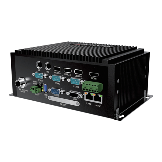
Chapter 2 Basics Product overview MicroBox-7824-E01 Rear Left Right Bottom Front... - Page 9 I/O Panel 11 10 1. PS/2 Mouse connector 8. CFAST card slot 2. PS/2 Keyboard connector 9. USB port 3. USB ports 10. Power LED(up)/HDD LED(down) indicator 4. HDMI port 11. 24V DC-IN power connector 5. GPIO port 12. Battery power input connector 6.
- Page 10 MicroBox-7824-E02 Rear Left Right Front...
- Page 11 I/O Panel 11 10 1. PS/2 Mouse connector 7. CFAST card slot 2. PS/2 Keyboard connector 8. Serial ports (COM1) 3. USB2.0 port x 3 9. USB3.0 port x 1 4. HDMI port 10. Power LED(up)/HDD LED(down) indicator 5. RJ45 LAN port x 2 11.
-
Page 12: Physical Dimensions
MicroBox-7824-E01 201.4 mm 7.93" Front View 88.1 mm 3.47" 224.4 mm 8.84" 212.6 mm 8.37" Top View 140.5 mm 108.0 mm 5.53" 4.25" L(Overall length) H(Overall height) D(Overall width) Weight MicroBox-7824B-E01 8.84”/224.4mm 3.47”/88.1mm 5.53”/140.5 mm 5.1 lb/2.3 kg... - Page 13 MicroBox-7824-E02 173.0 mm 6.81" Front View 63.5 mm 2.50" 195.8mm 7.71" 185.0 mm 7.28" Top View 81.0mm 116.5 mm 3.19" 4.59" L(Overall length) H(Overall height) D(Overall width) Weight MicroBox-7824B-E02 7.71”/195.8mm 2.50”/63.5mm 4.59”/116.5 mm 4.4lb/2.0 kg...
-
Page 14: Chapter 3 Connections
Chapter 3 Connections This section describes connections/connectors available on MicroBox-7824B E-Series microbox computer. Connectors are located on the front panel of MicroBox-7824B-E01 microbox computer. Connectors are located on the front panel of MicroBox-7824B-E02 microbox computer. -
Page 15: Pins In The Serial Port(Com1~Com4)
Pins in the serial port(COM1~COM4) 1 2 3 4 5 6 7 8 9 Pin NO. Definition(RS-232 mode) Definition(RS-422/RS-485 mode) DCD, data carrier detect TX-, Transmit data ground (RS-422/RS-485) RXD, Receive data TX+, Transmit data(RS-422/RS-485) TXD, Transmit data RX+, Receive data (RS-422) DTR, Data terminal ready RX-, Receive data ground (RS-422) GND, Signal ground... -
Page 16: Pins In The Vga Port
Pins in the VGA port Pin NO. Pin Assignment Definition VGA R VGA Red signal VGA G VGA Green signal VGA B VGA Blue signal No connection Ground Ground Ground Ground No connection Ground No connection CRT DDC Data The data of display data channel VGA HS VGA H-Sync signal VGA VS... -
Page 17: Pins In The Gpio Port (Only For Microbox-7824B-E01)
Pins in the GPIO port (only for MicroBox-7824B-E01) 9 10 The GPIO (General Purpose Input/Output) port is optional and can be used as expansion input or output ports by software routines as needed. Pin NO. Pin Assignment Definition +V5S +V5S... -
Page 18: Pins In The Dc-In Power Connector
Pins in the DC-IN power connector Pin NO. Definition Pin NO. Definition... -
Page 19: Mounting The Microbox Computer
Mounting the MicroBox computer 1. Wall mounting There are two methods to mount the MicroBox-7824B E-Series industrial microbox computer: Wall and DIN-rail mounting. The MicroBox-7824B E-Series microbox computer can be placed on a shelf, table, or mounted onto a wall or board. To mount it onto a wall or board, you will require the mounting screws found in the accessory box. - Page 20 Step3. Tighten the screws and make sure the MicroBox-7824B E-Series computer is correctly and securely seated onto the board or wall. Screw tightened It is very important to place the unit in a suitable environment. Make sure the area is well ventilated, out of direct sunlight, away from sources of excessive dust, dirt, heat, water, moisture and vibration.
- Page 21 2. DIN-Rail mounting Please follow the steps as shown below to mount the industrial computer via DIN- Rail. Step1. Place the metal clasp on the back of the MicroBox-7824B E-Series microbox computer, and screw it in using “#6-32UNC” sized screws. Metal clasp Metal clasp Step2.
- Page 22 Step3. Snap the metal clasp onto the Din-rail to mount the MicroBox-7824B E-Series microbox computer onto the wall or board. Step4. You can also slide the metal clasp around the Din-rail to move the computer to a desired position. • To remove the MicroBox-7824B E-Series industrial microbox computer from Din-rail, press down the two iron loop springs built-in the metal clasp down on the rail to loose it, then remove the MicroBox-7824B E-Series from the rail.
-
Page 23: Connecting To Display
• Connect one end of the VGA cable to the VGA port of the MicroBox-7824B E-Series fanless industrial microbox computer. Connect the other end of the VGA cable to the VGA port of a display. MicroBox-7824B-E01 Display VGA port VGA port VGA cable(not supplied) 2. -
Page 24: Connecting To Touch Screen
USB port or serial port(COM1~COM4 port) of the MicroBox-7824B E-Series fanless industrial microbox computer. Connect the other end of the USB cable or serial data cable to the USB port or serial port of a display. MicroBox-7824B-E01 Display USB port... -
Page 25: Connecting To Network
PS2 keyboard jack PS2 mouse jack MicroBox-7824B-E01 Keyboard Mouse Figure 2 Connecting to network • Connect one end of the RJ45 LAN cable to the LAN port of the MicroBox-7824B E-Series computer. Connect the other end of the RJ45 LAN cable to the LAN port of a modem. -
Page 26: Connecting The Power Supply
• Connect one end of the 72W DIN-Rail AC/DC power supply to the DC-in(24V) power connector of the MicroBox-7824B E-Series fanless industrial microbox computer. Connect the other end of 72W DIN-Rail AC/DC power supply to an AC outlet.Connect Power and Cable: MicroBox-7824B-E01 AC outlet 72W DIN-Rail Power supply(supplied) - Page 27 The AC to DC 24V power supply provided with the MicroBox-7824B E-Series fanless industrial microbox computer does not have environmental protection. In order to meet a degree of protection, the power supply has to be installed in a specific IP rating enclosure. Step1 Step2 Step3 Industrial Enclosure Screws DIN-rail Power supply In order to correctly install the power supply, specific dimensions for the power supply are indicated in the diagram below. Side View Front View Top View...
-
Page 28: Connecting The Battery Power (Only For Microbox-7824B-E01)
Connecting to battery power (only for MicroBox-7824B-E01) Use battery power when you’re away from a power AC outlet. Follow steps below to connect to the battery. The additional battery are optional and can be purchased separately through Arista Corporation. • Connect one end of the battery cable to the Battery power input connector of the MicroBox- 7824B-E01 fanless industrial microbox computer. -
Page 29: Installing Memory Module/Expansion Card
Installing memory module/expansion card Before you install the memory module or expansion card, please follow the instructions below to open the chassis of the MicroBox-7824B E-Series fanless industrial microbox computer. 1. Remove the six screws on both sides of the bottom case( Figure 1). 2. - Page 30 2. Insert the DIMM into the slot at 45-degree angle, then push it in until the golden finger on the DIMM is deeply inserted into the DIMM slot. 3. Firmly press the DIMM down to lock the module in place. Removing the memory module Follow these steps to remove the DIMM. 1. Use your finger to simply push away the retaining clips on both sides of the DIMM outward to unlock the DIMM.
- Page 31 Installing expansion card The MINI-PCIE slot supports PCIE cards such as a Wi-Fi LAN card, mSATA SSD, SCSI card, USBcard, and other cards that comply with PCIE specifications. The following figure shows a Wi-Fi LAN card installed on the MINI-PCIE slot. Follow the steps outlined below to install a Wi-Fi LAN card. 1. Locate the Wi-Fi LAN card on MINI-PCIE slot and align the notch on the card with the key on the slot.
-
Page 32: Chapter 4 Bios Setup
Chapter 4 BIOS Setup Introduction The computer uses latest “American Megatrends Inc.” BIOS with support for Windows Plug and Play. The CMOS chip on the motherboard contains the ROM setup instructions for configuring the built-in motherboard BIOS. The BIOS (Basic Input and Output System) Setup Utility displays the system’s configuration status and provides you with options to set system parameters. -
Page 33: Entering The Setup
Entering the Setup When you power on the system, BIOS enters the Power-On Self Test (POST) routines. POST is a series of built-in diagnostics performed by the BIOS. After the POST routines are completed, the following message appears: Press the Delete key to access BIOS Setup Utility. Resetting the default CMOS values When powering on for the first time, the POST screen may show a “CMOS Settings Wrong”... - Page 34 The default BIOS setting for this built-in motherboard apply for most conditions with optimum performance. We do not suggest users change the default values in the BIOS setup and take no responsibility to any damage caused by changing the BIOS settings. BIOS navigation keys The BIOS navigation keys are listed below: FUNCTION...
-
Page 35: M A I N M E N
Main Menu When you enter the BIOS SETUP UTILITY, the Main menu will appear and display the system overview. You can set the system clock in this main menu. BIOS Information This item shows the current BIOS information, including BIOS Version, Build date and time. EC Information This item shows the current EC information, including EC Version. -
Page 36: Advanced Menu
Advanced Menu Important: Be cautious when changing the setting of advance menu items. Incorrect field values can cause the system to malfunction. ACPI Settings Scroll to this item and press <Enter> to view the following screen: ACPI Sleep State [S3 (Suspend to RAM)] Select the highest ACPI sleep state, the system will resume when the SUSPEND button is pressed. - Page 37 FB1216 Super IO Configuration Scroll to this item and press <Enter> to view the following screen: Serial Port1/Port2/Port3/Port4 Configuration Serial port1/port2/port3/port4(Enabled) Use this option to enable or disable the use of serial ports. Change settings(Auto) Select an optimal settings for Super IO device. Type select(RS232) Select serial port type(RS232,RS422,RS485).
- Page 38 S5 RTC Wake Settings Scroll to this item and press <Enter> to view the following screen: Wake system from S5(Disabled) Use this item to enable or disable system wake on alarm event. Select Fixed Time. system will wake on the hr::min::sec specified. Select Dynamic Time, system will wake on the current time + Increase minute(s).
- Page 39 CPU Configuration Scroll to this item and press <Enter> to view the following screen: Socket 0 CPU information Use this item to view Socket 0 CPU information. Intel Virtualization Technology(Enabled) Most of the time, hardware virtualization technology extensions should be enabled in motherboard BIOS in order to run recent OS and applications.
- Page 40 IDE Configuration Scroll to this item and press <Enter> to view the following screen: SATA Port1~2 dynamically detect whether there are SATA devices on motherboard. If devices are connected with the corresponding ports, then it will display the SATA device type. Otherwise, it will display “Not Present”.
- Page 41 Miscellaneous Configuration Scroll to this item and press <Enter> to view the following screen: OS selection (Windows 7) Use this option to select the operating system for the computer. Press <Esc> to return to the Advanced Menu screen.
- Page 42 USB Configuration Scroll to this item and press <Enter> to view the following screen: Legacy USB Support (Enabled) Use this option to enable USB mouse and USB keyboard support. ENABLED option enables legacy USB support. AUTO option disables legacy support if no USB devices are connected. DISABLED option will keep USB devices available only for EFI applications.
-
Page 43: C H I P S E T M E N
Chipset Menu The chipset menu is for the Host Bridge chipset, South Bridge chipset and other system. Since features in this section are related to the chipset on the CPU board and are completely optimized, you are not recommended to change default settings in this setup table unless well oriented with chipset features.Mus North Bridge microbox computer Scroll to this item and press <Enter>... - Page 44 LCD Control Scroll to this item and press <Enter> to view the following screen: Primary IGFx Boot display (VBIOS Default) Select the video device which will be activated during POST. This has no effect if external graphics present. Secondary boot display selection will appear based on your selection. VGA modes will be supported only on primary display.
- Page 45 South Bridge Scroll to this item and press <Enter> to view the following screen: Azalia HD Audio Use this option to control detection of the Azalia device. Azalia controller(Enabled) Disabled: Azalia will be unconditionally disabled. Enabled: Azalia will be unconditionally enabled. Auto: Azalia will enabled if present disabled otherwise.
-
Page 46: Security Menu
Security Menu The Security Menu allows you to set Administrator and User password. If ONLY administrator password is set, it only allow access to setup when entering setup. If ONLY the user’s password is set, power on password must be entered to boot or enter Setup. In Setup, user will have administrator rights. -
Page 47: Boot Menu
Boot Menu The Boot Menu allows changing in the system boot options. Bootup Num-lock state (ON) If this item is set to “On”, it will automatically activate the Numeric Lock funcition after boot-up. UPS FUNCTION (OFF) This item allows the Uninterruptible Power System(UPS) setting. Set this item to “OFF”, work well with the system unit using battery power when sudden power lost occurs. -
Page 48: Save&Exit Menu
Save & Exit Menu The Save & Exit Menu save and exit the setup utility. Save Changes and Exit The following message, “Save configuration changes and exit setup?” Select [OK] to save changes and exit the UEFI SETUP UTILITY. Discard Changes and Exit The following message, “Discard changes and exit setup?”... -
Page 49: Chapter 5 Appendix
Chapter 5 Appendix Care and Maintenance Regular maintenance of the MicroBox-7824B E-Series fanless industrial microbox computer can help prevent damage or downtime. Service should be performed by qualified and authorized personnel. Make sure the computer is powered down and unplugged before removing the cover or working on internal components. -
Page 50: Product Limited Warranty
(invoice date),Arista Corporation will repair or replace with new or refurbished product or parts. • Arista Corporation holds every right to decide for repair or replacement of any product or part. During the “labor” limited warranty period there will be no charge for labor and during the “parts”... - Page 51 • Products will not be accepted by Arista RMA department if it is not accompanied by a valid RMA number. It should clearly marked on the outside of the package.
- Page 52 • No Credit DOA: No credit will be given to the customer for DOA products received by Arista beyond 30 calendar days after the invoice date. No credit will be given to all non- cancellable, non-returnable, custom order parts.
- Page 53 7. RMA Transportation Policy Product Non-Acceptance • Products will not be accepted by Arista Corporation if not accompanied by a valid RMA number, which must be clearly marked on the outside of the package. • Any products refused by Arista will incur fees and/or charges applied by the shipping carrier, and shall be the sole liability of the original shipper.
- Page 54 • Arista Corporation is not liable for incidental or consequential damages resulting from the use of Arista products or arising out of any breach of Arista’s full limited warranty. • Under no equitable theory shall Arista Corporation be held liable for monetary and/ or non-monetary damages resulting from the normal or abnormal usage of our products.
-
Page 55: Disposal And Recycling Information
However, as the product goes under continuous upgrades and changes, the final device may have slight differences. The contents of this manual are subject to changes without prior notice, and Arista shall not be liable for any errors contained herein or for incide or consequential damages in connection with the furnishing, performance, or use of this manual. - Page 56 Talk to us. We listen. Arista Corporation 40675 Encyclopedia Circle, Fremont, CA 94538 U.S.A. Tel: (510) 226-1800 Fax: (510) 226-1890 http://www.goarista.com...
Need help?
Do you have a question about the MicroBox-7824B-E01 and is the answer not in the manual?
Questions and answers