Table of Contents
Advertisement
Sales and Service
Centers and
Warehouses:
Oshkosh, Wisconsin
Toll Free: 1-800-472-9464
Fax: 1-920-236-4156
Fort Worth, Texas
Phone: 1-817-535-2183
Fax: 1-817-531-1163
Kent, Washington
Phone: 1-360-575-9917
Fax: 1-360-575-9706
Manufacturing
Facilities:
Oshkosh, WI
Direct Sales
Managers and
Technical Specialists
in Major Cities
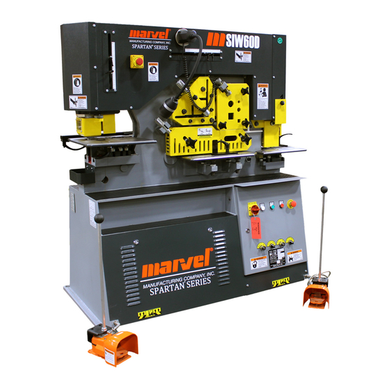
IRONWORKER
For IW66D/DX, IW88D/DX, IW110D/DX, IW135DX
Safety
Installation
Operation
Maintenance
Parts Catalog
Part No. PL/OMIW-2CYL_V2 06/14
Record your machine's serial number here:
________________________________________
Corporate Office and Service Center:
Toll Free 1-800-4-SAWING (1-800-472-9464)
Copyright © 2007 Marvel Manufacturing Company, INC.
and IW180 DX
3501 Marvel Drive
Oshkosh, WI 54902
Phone (920) 236-7200
Fax (920) 236-4156
www.sawing.com
Advertisement
Table of Contents

Related Manuals for Marvel SPARTAN IRONWORKER


Summary of Contents for Marvel SPARTAN IRONWORKER
- Page 1 Oshkosh, WI Direct Sales Managers and Technical Specialists in Major Cities Corporate Office and Service Center: 3501 Marvel Drive Oshkosh, WI 54902 Phone (920) 236-7200 Fax (920) 236-4156 Toll Free 1-800-4-SAWING (1-800-472-9464) www.sawing.com Copyright © 2007 Marvel Manufacturing Company, INC.
- Page 2 Marvel Manufacturing Co. manner. All guards must be in place, and Inc. safety glasses and other applicable safety clothing must always be used. The machine must be inspected and maintained regularly. © MARVEL MFG. CO., INC. MANUAL PL/OMIW-2CYL_V2 (08/07)
-
Page 3: Table Of Contents
MACHINE DESCRIPTION ........................ C-1 PUNCHING STATION ........................D-1 NOTCHING STATION ........................E-1 ANGLE SHEARING STATION ......................F-1 BAR SHEARING STATION ....................... G-1 FLAT BAR SHEARING STATION ....................H-1 MAINTENANCE ........................... J-1 REPAIR PARTS ............................ P-1 © MARVEL MFG. CO., INC. MANUAL PL/OMIW-2CYL_V2(08/07) - Page 4 A MESSAGE OF SAFETY SPARTAN IRONWORKER THIS PAGE LEFT BLANK INTENTIONALLY © MARVEL MFG. CO., INC. MANUAL PL/OMIW-2CYL_V2 (08/07)
- Page 5 Older equipment may not meet current standards and may have been modified outside the control of Marvel Manufacturing Co., Inc. While we are happy to support your use of this equipment, we ask that you take whatever means necessary to safeguard your operators.
-
Page 6: Safety
SAFETY SPARTAN IRONWORKER SPARTAN SAW SAFETY WHO MAY USE THIS MACHINE? Machinery sold by Marvel Manufacturing Co., Inc. is to be installed, operated, and maintained by people familiar with industrial machinery, the hazards associated with industrial machinery environment in which it is used, and the accepted methods of safeguarding against those hazards. -
Page 7: Safety Signal Words
• Turn off the machine's power at its main electrical disconnect switch and lock it in the "Off" position before adjusting, servicing, or cleaning the saw. © MARVEL MFG. CO., INC. MANUAL PL/OMiW-2CYL_V2 (08/07) © MARVEL MFG. CO., INC. MANUAL 8SDN10871N (04/08) -
Page 8: Handle Chemicals Safely
• Never use compressed air to remove debris from the machine. The flying debris can cause serious personal injury. Remove debris with a brush. © MARVEL MFG. CO., INC. MANUAL PL/OMIW-2CYL-V2 (08//07) © MARVEL MFG. CO., INC. MANUAL 8SDN10871N (04/08) -
Page 9: Safe Material Handling
(line) side of the main fuses. Keep hands and tools away from the top of the electrical panel’s main fuses. © MARVEL MFG. CO., INC. MANUAL PL/OMiW-2CYL_V2 (08/07) © MARVEL MFG. CO., INC. MANUAL 8SDN10871N (04/08) -
Page 10: Hazardous Metals
Standard machines sold by Marvel Manufacturing Co. Inc. do not meet those special requirements. HIGH PRESSURE FLUIDS • Fluid escaping under pressure can penetrate skin and cause serious injury and death. -
Page 11: Keep The Machine Safe
• Stop the machine before reaching into the cutting area or any area with moving parts. • Always use the tooling guards. • Report unsafe conditions to your employer. © MARVEL MFG. CO., INC. MANUAL PL/OMiW-2CYL_V2 (08/07) © MARVEL MFG. CO., INC. MANUAL 8SDN10871N (04/08) -
Page 12: Service The Machine Safely
Always maintain a safe footing, a firm hand hold, and never jump off the machine. © MARVEL MFG. CO., INC. MANUAL PL/OMIW-2CYL-V2 (08//07) © MARVEL MFG. CO., INC. MANUAL 8SDN10871N (04/08) - Page 13 SPARTAN IRONWORKER SAFETY THIS PAGE LEFT BLANK INTENTIONALLY © MARVEL MFG. CO., INC. MANUAL PL/OMiW-2CYL_V2 (08/07)
- Page 14 When transporting the machine with a crane, hook Stock Movement - Leave space around the the crane to the eye bolt on top of the machine machine for loading and unloading stock. (A). © MARVEL MFG. CO., INC. MANUAL PL/OMiW-2CYL_V2 (08/07)
-
Page 15: Installation
(B). DANGER Hazardous voltage. Will cause serious injury or death. Turn off supply electricity at your facility’s circuit breaker before making electrical connections to the machine. © MARVEL MFG. CO., INC. MANUAL PL/OMIW-2CYL-V2 (08//07) - Page 16 The main power leads L1, L2, and L3 (C) connect to the • Turn the Emergency Stop pushbuttons terminals at the bottom of the terminal strip. The ground clockwise to reset them. © MARVEL MFG. CO., INC. MANUAL PL/OMiW-2CYL_V2 (08/07)
- Page 17 • Tools and other material left on the machine electricity your facility’s • Overall condition and readiness for use circuit breaker before making electrical connections to the machine. Turn off the machine's supply voltage at your facility's circuit breaker. © MARVEL MFG. CO., INC. MANUAL PL/OMIW-2CYL-V2 (08//07)
-
Page 18: General Specifications
IW110DX/2 10HP 26.5A/13.25A 7,608 lbs 75Db +/- 5dB IW135D 15HP 37.5A/18.75A 7,365 lbs 75Db +/- 5dB IW135DX 15HP 37.5A/18.75A 8,710 lbs 75Db +/- 5dB IW180DX 20HP 50.5A/25.25A 10,915 lbs 75Db +/- 5dB © MARVEL MFG. CO., INC. MANUAL PL/OMiW-2CYL_V2 (08/07) - Page 19 Auto / Manual Switch Shear / Notch Switch Pump On Pushbutton Pump Off Pushbutton Normal Jog Switch Door Lock Emergency Stop Pushbutton Punching Station Foot Switch Notching / Shearing Foot Switch Electric Back Gauge © MARVEL MFG. CO., INC. MANUAL PL/OMiW-2CYL_V2 (08/07)
-
Page 20: Machine Description
Notching Station (see page E-1) Punching Station (see page D-1) Slug Bin Stripper (see page D-3) Notching / Shearing Foot Switch (see page C-7) Moveable Worklight Emergency Stop Pushbutton (see page C-6) © MARVEL MFG. CO., INC. MANUAL PL/OMIW-2CYL-V2 (08//07) -
Page 21: Machine Overview - Discharge Side
Punching Station / Stripper (see page D-1) Punching Station Stroke Adjustment (see page D-9) Die Holder (see page D-6) Notching Station (see page E-1) Slug Bin Electric Back Gauge (see page C-7) © MARVEL MFG. CO., INC. MANUAL PL/OMiW-2CYL_V2 (08/07) -
Page 22: Machine Overview - Operator's Panel
Auto / Manual switch (see page C-5) Shear / Notch switch (see page C-5) Pump Off pushbutton (see page C-6) Pump On pushbutton (see page C-5) Normal / Jog switch (see page C-6) Door Lock (see page C-6) © MARVEL MFG. CO., INC. MANUAL PL/OMIW-2CYL-V2 (08//07) -
Page 23: Important
The machine's electrical circuits ON - "I" are connected to the power source and the machine can be operated. © MARVEL MFG. CO., INC. MANUAL PL/OMiW-2CYL_V2 (08/07) -
Page 24: Pump On Pushbutton
"Normal / Jog" switch together affect the when the foot switch is released. operation of the punching station. Jog - Use the "Jog" position during machine set-up. In this position the tooling descends while the foot switch is © MARVEL MFG. CO., INC. MANUAL PL/OMIW-2CYL-V2 (08//07) -
Page 25: Notching / Shearing Foot Switch
Normal / Jog switch is in the "Jog" position, pressing the foot switch all the way down causes the tooling to move down into the work area. When the foot switch is released the tooling maintains its position. © MARVEL MFG. CO., INC. MANUAL PL/OMiW-2CYL_V2 (08/07) - Page 26 (E) and turn the collar until the measured shear length of the part is indicated by the rear of the collar and re- tighten the set screw. © MARVEL MFG. CO., INC. MANUAL PL/OMIW-2CYL-V2 (08//07)
-
Page 27: Punching Station
12” (20” DX) 12” (20” DX) 20” Max. Web (Channel) 7” 7” 7” 7” 7” Stroke Length 4” 4” 4” 4” 4” Cycles / Min (3/4”) Work Height 41-1/4” 41-1/4” 41-1/4” 41-1/4” 41-1/4” © MARVEL MFG. CO., INC. MANUAL PL/OMiW-2CYL_V2 (08/07) - Page 28 After the button is pressed it remains in the off position, preventing the machine from being restarted, until the button is reset by turning it clockwise. © MARVEL MFG. CO., INC. MANUAL PL/OMIW-2CYL-V2 (08//07)
- Page 29 Swivel the washer over the end of the insert and tighten the cap screw (E). The stripper opens by pressing down on the tab (A). A hole in the tab engages a pin on the © MARVEL MFG. CO., INC. MANUAL PL/OMiW-2CYL_V2 (08/07)
- Page 30 (C). Though this is an material can be slid under the stripper exaggerated example, even a slight misalignment with little or no resistance. of the stripper with the work material can result in a damaged punch. © MARVEL MFG. CO., INC. MANUAL PL/OMIW-2CYL-V2 (08//07)
- Page 31 The punch holder consists of the retaining thread (A), coupling nut (B), and punch sleeve (C). The quick-change feature, as it name implies, allows broken and worn punches to be quickly © MARVEL MFG. CO., INC. MANUAL PL/OMiW-2CYL_V2 (08/07)
- Page 32 Tighten the coupling nut with the spanner Reversing the Die Holder wrench provided. The die holder has two die wells; one large (E) and one small (F). The punch and die © MARVEL MFG. CO., INC. MANUAL PL/OMIW-2CYL-V2 (08//07)
- Page 33 The top of the die must be flush with, or slightly higher than, the top of the die holder. Six socket head cap screws (C) hold the die holder in place. © MARVEL MFG. CO., INC. MANUAL PL/OMiW-2CYL_V2 (08/07)
- Page 34 Note: Make sure the Emergency Stop pushbutton is reset. WARNING Avoid serious injury. When foot switch pressed, the punch ram will descend. Keep hands and arms away from the punch and die. © MARVEL MFG. CO., INC. MANUAL PL/OMIW-2CYL-V2 (08//07)
- Page 35 (D) are tight. Important: The forces exerted on the punch and die will cause them to become mis-aligned. It is important to visually check the alignment © MARVEL MFG. CO., INC. MANUAL PL/OMiW-2CYL_V2 (08/07)
- Page 36 Example #1 - Round holes: When punching a 1/2" diameter hole in 3/8" thick material, you would Important: When the punch cylinder is at its use a 17/32" diameter die. upper or lower limit of travel the stroke D-10 © MARVEL MFG. CO., INC. MANUAL PL/OMIW-2CYL-V2 (08//07)
- Page 37 WD40® or CRC®. Do not use heavy oils such as motor oil or any type of grease. D-11 © MARVEL MFG. CO., INC. MANUAL PL/OMiW-2CYL_V2 (08/07)
- Page 38 (tensile strength), and the size of the hole being punched. A quick-reference chart for punching round holes is provided on the following page. Avoid serious injury. Never WARNING exceed the machine’s punching capacity. D-12 © MARVEL MFG. CO., INC. MANUAL PL/OMIW-2CYL-V2 (08//07)
- Page 39 *This Chart is based on punching mild steel with a 65,000 lb. shear strength. All information in this chart should be verified before applying it to your work particularly when using combinations that approach the machine’s maximum tonnage capacity. D-13 © MARVEL MFG. CO., INC. MANUAL PL/OMiW-2CYL_V2 (08/07)
- Page 40 Normal / Jog switch to "Jog". electrical disconnect switch and lock it in o Press the Emergency Stop pushbutton. the "Off" position. o Make sure all guards and covers are in place and function properly. D-14 © MARVEL MFG. CO., INC. MANUAL PL/OMIW-2CYL-V2 (08//07)
- Page 41 To continue punching the same material using the same punch size, Punch Operation repeat steps 3 through 5. Remember to lubricate the punch every 5 to 10 punches D-15 © MARVEL MFG. CO., INC. MANUAL PL/OMiW-2CYL_V2 (08/07)
- Page 42 1 of "Punching Station Set-up", page D-13. If you are done punching, continue with step 7. Press the Emergency Stop pushbutton. Turn the Main Electrical Disconnect Switch off. D-16 © MARVEL MFG. CO., INC. MANUAL PL/OMIW-2CYL-V2 (08//07)
- Page 43 3” x 1 / 2” 4” x 1 / 2” 4” x 5/8” (optional) Work Height 35-3 / 4” 36 – 1 / 2” 36” 36- 1 / 4” 36- 1 / 4” © MARVEL MFG. CO., INC. MANUAL PL/OMiW-2CYL_V2 (08/07)
-
Page 44: Notching Station
Machine Description section, clockwise. page C-7. WARNING Emergency Stop pushbutton does disconnect components from the power supply. Avoid serious injury or death by turning the machine's power off at the Main Electrical © MARVEL MFG. CO., INC. MANUAL PL/OMIW-2CYL-V2 (08//07) - Page 45 The stripper must be correctly adjusted to provide notching process, or when the blade shows visible uniform contact with the work piece while the signs of wear. upper blade is retracting from the workpiece. © MARVEL MFG. CO., INC. MANUAL PL/OMiW-2CYL_V2 (08/07)
- Page 46 Features of the bolster include the lower blades (A), lock-down screws (B), bolster adjusting screws (C), and bolster hold-back screws (D). In this photo the work table has been removed for illustration purposes. © MARVEL MFG. CO., INC. MANUAL PL/OMIW-2CYL-V2 (08//07)
- Page 47 Loosen the bolster adjusting screws (I). CAUTION Avoid injury. The bolster is heavy. Use care when removing it from the machine. Slide the bolster off the end of the machine. © MARVEL MFG. CO., INC. MANUAL PL/OMiW-2CYL_V2 (08/07)
- Page 48 However, if you find the notcher does not cut completely through the material, or retract high enough to allow material to be placed under it, © MARVEL MFG. CO., INC. MANUAL PL/OMIW-2CYL-V2 (08//07)
- Page 49 You are familiar with the function and location of the machine's components. You have inspected the machine and determined it is in safe, working condition (for example: no missing, altered or broken parts; © MARVEL MFG. CO., INC. MANUAL PL/OMiW-2CYL_V2 (08/07)
- Page 50 You have read and understand all of a low hydraulic fluid level. the safety and instructional material supplied Damage to the machine will with the machine by Marvel Mfg. Co. Inc., occur. including the Operator's manual and the safety and warning signs attached to the Notching Station Set-up machine.
- Page 51 Press the foot switch all the way down and hold it until the upper blade has cut through the material. Release the foot switch to retract the notcher. © MARVEL MFG. CO., INC. MANUAL PL/OMiW-2CYL_V2 (08/07)
- Page 52 Marvel Stroke Adjustment Mfg. Co., including the Operator's Angle Shear Capacity F-10 manual and the safety and warning Angle Shear Operation F-10 signs attached to the machine. © MARVEL MFG. CO., INC. MANUAL PL/OMiW-2CYL_V2 (08/07)
-
Page 53: Angle Shearing Station
The time delay between when the stock contacts the sensor and when the shear is activated can be adjusted from 0 seconds to 3 seconds with a timer in the electrical enclosure. © MARVEL MFG. CO., INC. MANUAL PL/OMIW-2CYL-V2 (08//07) - Page 54 (A) will contact it at the desired cut-off length. GUIDES / GUARD The guard (A) protects the operator from the shear blades and helps provides support for the Angle stock is shown here positioned for a 90 work piece. shear. © MARVEL MFG. CO., INC. MANUAL PL/OMiW-2CYL_V2 (08/07)
- Page 55 After inserting the work piece, turn the holddown's knurled knob clockwise until it holds the work piece firmly in place. Note: When shearing stock in either of the angle shear's 450 positions the holddown cannot be used. © MARVEL MFG. CO., INC. MANUAL PL/OMIW-2CYL-V2 (08//07)
- Page 56 (F). Remove the socket head cap screws that hold the guard in place and carefully remove the guard. © MARVEL MFG. CO., INC. MANUAL PL/OMiW-2CYL_V2 (08/07)
- Page 57 Tighten the four socket head cap screws (B) that help lock the bolster in position. © MARVEL MFG. CO., INC. MANUAL PL/OMIW-2CYL-V2 (08//07)
- Page 58 The stationary blades need to be replaced when the work piece develops burrs as a result of the shearing process or when the blades show visible signs of wear. Make sure the moveable blade is all the way up. © MARVEL MFG. CO., INC. MANUAL PL/OMiW-2CYL_V2 (08/07)
- Page 59 Press the foot switch until the moveable CAUTION Avoid injury. The guard weighs blade descends behind the stationary 22 lbs. Use care when removing blades and then release the foot switch. it from the machine. © MARVEL MFG. CO., INC. MANUAL PL/OMIW-2CYL-V2 (08//07)
- Page 60 Loosen the 4 socket head cap screws (B CAUTION Avoid injury. The guard weighs and C). 22 lbs. Use care when lifting and installing the guard. Re-install the guard removed in step 2. © MARVEL MFG. CO., INC. MANUAL PL/OMiW-2CYL_V2 (08/07)
- Page 61 Safe operation of this machine depends on you, the operator. Right Collar (C): This collar controls the upward travel limit of the shear only when the Shear/ Do not operate the machine unless: F-10 © MARVEL MFG. CO., INC. MANUAL PL/OMIW-2CYL-V2 (08//07)
- Page 62 Note: If the hydraulic pump does not come on surrounding area. make sure the Emergency Stop pushbutton(s) are o Inspect the machine for damage, leaks, and reset. alterations. Repair before operating. F-11 © MARVEL MFG. CO., INC. MANUAL PL/OMiW-2CYL_V2 (08/07)
- Page 63 Never place any guards. part of your body inside the Tighten the holddown guards. against the material. Note: When using either of the angle shear's 45° shearing positions the holddown cannot be used. F-12 © MARVEL MFG. CO., INC. MANUAL PL/OMIW-2CYL-V2 (08//07)
- Page 64 To continue shearing, repeat step 3. If you are done shearing, continue with step 5. Press the Emergency Stop pushbutton. Turn the Main Electrical Disconnect Switch off. F-13 © MARVEL MFG. CO., INC. MANUAL PL/OMiW-2CYL_V2 (08/07)
- Page 65 You have read and understand all of the safety and instructional material Bar Shear Operation supplied with the machine by Marvel Mfg. Co., including the Operator's manual and the safety and warning signs attached to the machine. © MARVEL MFG. CO., INC. MANUAL PL/OMiW-2CYL_V2 (08/07)
-
Page 66: Bar Shearing Station
Important: These instruction only describe the desired position. The edge of the collar (D) set-up procedure to prepare the back gauge indicates the shear length setting. for operation. Operation of the shear with the © MARVEL MFG. CO., INC. MANUAL PL/OMIW-2CYL-V2 (08//07) - Page 67 Remove the two hand knobs (C) that hold the guard in place and carefully remove the guard. To Adjust the Guide / Guard: Loosen the two hand knobs (B). © MARVEL MFG. CO., INC. MANUAL PL/OMiW-2CYL_V2 (08/07)
- Page 68 WARNING Avoid serious injury. servicing the machine. Turn off the machine's power and lock it out before Turn main electrical disconnect switch and lock it in adjusting servicing machine. the "Off" position. © MARVEL MFG. CO., INC. MANUAL PL/OMIW-2CYL-V2 (08//07)
- Page 69 This collar should always be positioned fully right, against its stop. Moving this collar away from its stop prevents the shear from descending completely and results in incomplete cuts. © MARVEL MFG. CO., INC. MANUAL PL/OMiW-2CYL_V2 (08/07)
- Page 70 Perform the pre-operation checklist on Pre-Operation Checklist page G-6. This checklist must be completed at the beginning Position following switches of each shift and by each operator. indicated: o Safety First! Obey all warnings. © MARVEL MFG. CO., INC. MANUAL PL/OMIW-2CYL-V2 (08//07)
- Page 71 Keep away from moving parts when inserting the work material in the shear. Adjust the guide/guard as described on page G-3. © MARVEL MFG. CO., INC. MANUAL PL/OMiW-2CYL_V2 (08/07)
- Page 72 To continue shearing, repeat step 3. If you are done shearing, continue with step 6. Press the Emergency Stop pushbutton. Turn the Main Electrical Disconnect Switch off. © MARVEL MFG. CO., INC. MANUAL PL/OMIW-2CYL-V2 (08//07)
- Page 73 Flat Bar Shear Capacity material supplied with the machine Flat Bar Shear Operation by Marvel Mfg. Co., including the Operator's manual and the safety and warning signs attached to the machine. © MARVEL MFG. CO., INC. MANUAL PL/OMiW-2CYL_V2 (08/07)
-
Page 74: Flat Bar Shearing Station
Important: These instruction only describe the desired position. The edge of the collar (D) set-up procedure to prepare the back gauge indicates the shear length setting. for operation. Operation of the shear with the © MARVEL MFG. CO., INC. MANUAL PL/OMIW-2CYL-V2 (08//07) - Page 75 Turn main electrical disconnect switch and lock it in the "Off" position. Remove the two hand knobs (A) that secure the guard / holddown and remove the guard. © MARVEL MFG. CO., INC. MANUAL PL/OMiW-2CYL_V2 (08/07)
- Page 76 (item result of the shearing process, or when the blade "C", page H-6) and remove the blade. shows visible signs of wear. © MARVEL MFG. CO., INC. MANUAL PL/OMIW-2CYL-V2 (08//07)
- Page 77 Make sure the moveable blade that hold the work table in place. will not strike the stationary blade. Important: If it appears the moveable blade will strike the stationary blade, continue with step 10. © MARVEL MFG. CO., INC. MANUAL PL/OMiW-2CYL_V2 (08/07)
- Page 78 Adjust each collar to achieve the proper range of shear travel: Measure the clearance between the blades with a feeler gauge. The blades should have a uniform clearance of .010". Slightly loosen the socket head cap screws (C). © MARVEL MFG. CO., INC. MANUAL PL/OMIW-2CYL-V2 (08//07)
- Page 79 Angle Shearing station's upward travel is reduced. Station chapter before performing any steps in this section. Safe operation of this machine depends on you, the operator. © MARVEL MFG. CO., INC. MANUAL PL/OMiW-2CYL_V2 (08/07)
- Page 80 Emergency Stop pushbutton(s) are o Remove unnecessary tools and equipment reset. from the machine and surrounding area. o Inspect the machine for damage, leaks, and alterations. Repair before operating. © MARVEL MFG. CO., INC. MANUAL PL/OMIW-2CYL-V2 (08//07)
- Page 81 Never place any part of your body inside the WARNING Avoid serious injury. guards. shear will automatically cut when the work material is pushed through the flat bar shear and contacts the electric © MARVEL MFG. CO., INC. MANUAL PL/OMiW-2CYL_V2 (08/07)
- Page 82 To continue shearing, repeat step 3. If you are done shearing, continue with step 5. Press the Emergency Stop pushbutton. Turn the Main Electrical Disconnect Switch off. H-10 © MARVEL MFG. CO., INC. MANUAL PL/OMIW-2CYL-V2 (08//07)
- Page 83 If you need the help of a Spartan service premature wear. technician, contact your Spartan distributor or call Marvel Mfg. Co., Oshkosh, Wisconsin, at 1-800- 472-9464. © MARVEL MFG. CO., INC. MANUAL PL/OMiW-2CYL_V2 (08/07)
- Page 84 (A and B) every 8 operating hours. Clean grease fittings before lubricating. The hydraulic fluid level sight gauge is visible through a cut-out in the enclosure panels (A). © MARVEL MFG. CO., INC. MANUAL PL/OMIW-2CYL-V2 (08//07)
-
Page 85: Maintenance
(C) shows the fluid level is at 3/4 compartment access cover. full. CHANGING THE HYDRAULIC FLUID The hydraulic fluid must be changed at least once every year and any time it becomes dirty or contaminated. © MARVEL MFG. CO., INC. MANUAL PL/OMiW-2CYL_V2 (08/07) - Page 86 The adjusting screws (C) are locked in position by large locknuts (B). Tighten the adjusting screws (C) by turning them clockwise. Back each adjusting screw (C) out by turning them 1/3 of a turn counter- clockwise. © MARVEL MFG. CO., INC. MANUAL PL/OMIW-2CYL-V2 (08//07)
- Page 87 (B). Turn the adjusting set screws clockwise to tighten the punch ram. Do not over- tighten the adjusting screws. Operate the punch. The punch should move smoothly. © MARVEL MFG. CO., INC. MANUAL PL/OMiW-2CYL_V2 (08/07)
-
Page 88: Repair Parts
Punching Cylinder ......P-16 supplied with the machine are installed and functioning Electric Back Gauge ...... P-18 as designed. Shearing Cylinder ......P-19 Stroke Adjusters......P-21 Electrical Components....P-23 Hydraulic System ......P-24 © MARVEL MFG. CO., INC. MANUAL PL/OMiW-2CYL_V2 (08/07) - Page 89 Cable (2) 15-NP17 Warning Decal-Lockout IWM-3002001 Cover (2) IW66D IW45-NP4 Warning Decal-Gloves IWM-3102001 Cover (2) IW66DX 81-NP66 Warning Decal-Operator IWM-3202022 Cover IWM-1302022 Scrap Box Notch IWE-M611 Foot Switch (2) IWM-3002020 Guard, Notcher © MARVEL MFG. CO., INC. MANUAL PL/OMIW-2CYL-V2 (08//07)
-
Page 90: Operator's Side
IW45-NP3 Warning Decal-Shear 15-NP17 Warning Decal-Lockout 15-NP17 Warning Decal-Lockout IW45-NP4 Warning Decal-Gloves IW45-NP4 Warning Decal-Gloves 81-NP66 Warning Decal-Operator 81-NP66 Warning Decal-Operator IWM-1302022 Scrap Box Notch IWM-1302022 Scrap Box Notch IWM-2802013 Guard, Notcher © MARVEL MFG. CO., INC. MANUAL PL/OMiW-2CYL_V2 (08/07) - Page 91 Cover, IW66DX IWM-3002019 Chute IWM-3002003 Cover IW66D IWM-3102003 Cover IW66DX IWM-3002021 Hose Cover IWM-3002007 Punch Cover LH IW66D IWM-3102005 Punch Cover LH IW66DX IWM-3002014 Guard Angle Shear IWM-3002008 Cover Limit Switch IW66D © MARVEL MFG. CO., INC. MANUAL PL/OMIW-2CYL-V2 (08//07)
-
Page 92: Discharge Side
Description [Qty if more than 1] IWM-3602013 Guard Bar Shear IWM-3602008 Cover IWM-3602007 Cover IWM-3602012 Guard Flat Shear See Elect Gauge IWM-3602021 Cover IW135D IWM-3702005 Cover IW135DX IWM-3602014 Chute IWM-3602022 Cover IW135D IWM-3702006 Cover IW135DX © MARVEL MFG. CO., INC. MANUAL PL/OMiW-2CYL_V2 (08/07) - Page 93 M8 Hex Nut (2) IWM-1305012 T Nut (4) IWM-3206003 Stop M12 Flat Washer (4) IWM-1605009 Clamp (2) M12 Lock Washer (4) M10x40 Soc Hd Cap Scr (4) M12x50 Soc Hd Cap Scr (4) © MARVEL MFG. CO., INC. MANUAL PL/OMIW-2CYL-V2 (08//07)
-
Page 94: Notching Station
Part No. Description [Qty if more than 1] IWA-2606001 Blade Top IWM-3406001 Blade Top M18x35 Soc Hd cap Scr IWM-1306004 Stripper Left M12x30 Soc Hd cap Scr (4) M12 Lock Washer (4) © MARVEL MFG. CO., INC. MANUAL PL/OMiW-2CYL_V2 (08/07) - Page 95 Inc in Item 16 Spring Pin M16x50 Soc Hd Cap Scr (3) IWM-3007019 Hand Knob (2) M16 Lock Washer (3) M16 Flat Washer (2) IWM-3209900 Hold Down IWA-3009001 Rd/Sq Shear Blade Stationary IWM-3210900 Screw © MARVEL MFG. CO., INC. MANUAL PL/OMIW-2CYL-V2 (08//07)
-
Page 96: Angle And Bar Shear
IWM-1309004 Retainer (2) M10 Lock Washer (6) M12x20 Soc Hd Cap Scr (4) M20x35 Soc Hd Cap Scr (3) M10x40 Soc Set Scr (4) M20 Lock Washer (3) M10 Hex Nut (12) © MARVEL MFG. CO., INC. MANUAL PL/OMiW-2CYL_V2 (08/07) -
Page 97: Flat Shear
M12x40 Soc Hd Cap Scr (6) M12x40 Soc Hd Cap Scr (6) M12 Lock Washer (6) M12 Lock Washer (6) Models IW110D/2 and IW110DX/2 Models IW88D, & IW88DX Part No. Description [Qty if more than 1] P-10 © MARVEL MFG. CO., INC. MANUAL PL/OMIW-2CYL-V2 (08//07) - Page 98 T Nut (4) M14x40 Soc Hd Cap Scr (3) M12 x 40 Soc Hd Cap Scr (6) M14x55 Soc Hd Cap Scr (3) M12 Lock Washer (6) M14 Lock Washer (6) P-11 © MARVEL MFG. CO., INC. MANUAL PL/OMiW-2CYL_V2 (08/07)
- Page 99 SPARTAN IRONWORKER PUNCHING STATION P-12 © MARVEL MFG. CO., INC. MANUAL PL/OMIW-2CYL-V2 (08//07)
- Page 100 IWM-3205004 Bracket M10x50 Soc Set Scr M6x16 Flat Hd Soc Scr (4) M12 Flat Washer (2) IWM-3205008 Clamp IWM-1305011 T Nut (6) IWM-3205005 X Axis Guide Bar M16 Lock Washer (6) P-13 © MARVEL MFG. CO., INC. MANUAL PL/OMiW-2CYL_V2 (08/07)
- Page 101 Clamp Handle (2) M10x25 Soc Hd Cap Scr (4) IWM-RULER305 Ruler “D” Model IWM-RULER505 Ruler “DX” Model IWM-RULER02 Ruler X Axis IWM-3205010 Copper Slug (2) IWM-2211009 Copper Slug M6x10 Soc Set Scr IWM-06x10KEY P-14 © MARVEL MFG. CO., INC. MANUAL PL/OMIW-2CYL-V2 (08//07)
- Page 102 Description [Qty if more than 1] IWA- 3205014 Stripper Adjusting Screw (2) Spring Pin (2) IWA-STBH005 Hydraulic Stripper IWA-3205900 Hydraulic Stripper Cylinder (2) M12x25 Soc Hd Cap Scr (2) IWA-3205017 M22 Nut (2) P-15 © MARVEL MFG. CO., INC. MANUAL PL/OMiW-2CYL_V2 (08/07)
-
Page 103: Punching Station
M12 Hex Nut (2) Included with Seal Kit, Key 15 IWH-OLSK100SP Seal Kit Included with Seal Kit, Key 15 Included with Seal Kit, Key 15 Included with Seal Kit, Key 15 P-16 © MARVEL MFG. CO., INC. MANUAL PL/OMIW-2CYL-V2 (08//07) - Page 104 M14Lock Washer (7) M10x45 Soc Hd Cap Scr (2) M12x90Soc Set Scr (2) M12 Hex Nut (2) IWH-OLSK165SP Seal Kit Included with Seal Kit, Key 15 Included with Seal Kit, Key 15 P-17 © MARVEL MFG. CO., INC. MANUAL PL/OMiW-2CYL_V2 (08/07)
- Page 105 Main Rod, 1 Meter IWM-2211902L Maain Rod, 2 Meter M10 Lock Washer (3) IWE-PLT2 5 Male Connector IWM-3211001 Scale 1030 mm Part of Item 9 IWM-2211009 Copper Slug M6x8 Soc Set Scr P-18 © MARVEL MFG. CO., INC. MANUAL PL/OMIW-2CYL-V2 (08//07)
-
Page 106: Punching Cylinder
Included with Seal Kit, Key No. 11 IWM-3210003 Included with Seal Kit, Key No. 11 IWM-CPS65 Clip (2) Included with Seal Kit, Key No. 11 IWM-3010004 IWM-CPS65 Clip (2) M8x10 Soc Set Scr (2) IWH-OLSK60SS Seal Kit P-19 © MARVEL MFG. CO., INC. MANUAL PL/OMiW-2CYL_V2 (08/07) -
Page 107: Shearing Cylinder
Included with Seal Kit, Key No. 11 Included with Seal Kit, Key No. 11 Included with Seal Kit, Key No. 11 Included with Seal Kit, Key No. 11 Included with Seal Kit, Key No. 11 P-20 © MARVEL MFG. CO., INC. MANUAL PL/OMIW-2CYL-V2 (08//07) -
Page 108: Stroke Adjusters
STROKE ADJUSTERS SPARTAN IRONWORKER Shear Stroke Adjusters Punch Stroke Adjusters P-21 © MARVEL MFG. CO., INC. MANUAL PL/OMiW-2CYL_V2 (08/07) - Page 109 M8x50 Soc Hd Cap Scr M5x30 Soc Hd Cap Scr (10) M8 Lock Washer IWM-3204007Switch Dog (5) IWM-3204008Pointer (5) M6x10 Soc Set Scr (5) IWM-1304004Base IWM-1304005Post M6x15 Soc Hd Cap Scr (3) P-22 © MARVEL MFG. CO., INC. MANUAL PL/OMIW-2CYL-V2 (08//07)
- Page 110 Normal/Jog Switch IWE-PEN-5 IWE-PEB-003 Pump On Switch IWE-PEN-2 IWE-PEB0-004 Pump Off Switch IWE-PEN-3 IWE-PEB-005 Shear/Notch Switch IWE-PEN-6 Not Shown IWE-PEB-006 E- Stop Switch IWE-PEN-1 E Stop Nameplate IWE-PEA-1 Plastic Enclosure All Models P-23 © MARVEL MFG. CO., INC. MANUAL PL/OMiW-2CYL_V2 (08/07)
- Page 111 M10x25 Soc Hd Cap Scr (2) PHV-0144 Relief Valve M10 Lock Washer (2) IWM-2203016 Manifold PHE-0017 Strainer PHH-81000 1/2 x 1000 Hydraulic Hose IWM-1303008 Gasket PHH-82320 (88D) 1/2 x 2320 Hydraulic Hose P-24 © MARVEL MFG. CO., INC. MANUAL PL/OMIW-2CYL-V2 (08//07)
-
Page 112: Hydraulic System
PHH-83440 1/2 x 3440 Hydraulic Hose PHP-0041 Pump PHH-83290 1/2 x 3290 Hydraulic Hose M10x25 Soc Hd Cap Scr (2) PHH-121660 3/4 x 1660 Hydraulic Hose M10 Lock Washer (2) PHH-121850 3/4 x 1850 Hydraulic Hose P-25 © MARVEL MFG. CO., INC. MANUAL PL/OMiW-2CYL_V2 (08/07) - Page 113 1/2 x 1920 Hydraulic Hose PHV-0145 Control Valve (2) PHH-81900 (66D) 1/2 x 1900 Hydraulic Hose M5x40 Soc Hd Cap Scr (12) PHH-82080 (66DX) 1/2 x 2080 Hydraulic Hose PHV-0146 Control Valve P-26 © MARVEL MFG. CO., INC. MANUAL PL/OMIW-2CYL-V2 (08//07)
Need help?
Do you have a question about the SPARTAN IRONWORKER and is the answer not in the manual?
Questions and answers