Table of Contents
Advertisement
the benchmark for emc
M a n u a l
f o r
O p e r a t i o n
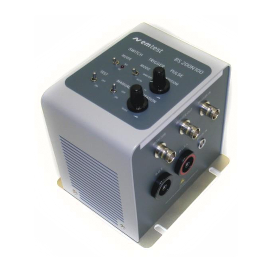
BS 200N100
BS 200N100.1
Electronic switch
for Voltage Transient testing
CABS 200N
Load impedance for BS200N100
RS-Box
Shunt resistor
R-Box LV124
The BS 200N100 is used to evaluate automotive electrical and
electronic components for conducted emissions of transients
along battery fed or switched supply lines of a Device Under
Test (DUT). A device under test which is considered a potential
source of conducted disturbances should be tested according to
ISO 7637 part 2. The BS 200N100 and BS 200N100.1 include
an electronic switch for repeatable switching of inductive loads
as specified in ISO 7637-2:2011 yet supporting former standard
editions.
Version: 1.12 / 30.08.2019
Replaces: 1.11 / 03.06.2017
Filename: UserManual-BS200N100-E-V1.12.doc
Printdate: 30.08.19
•
ISO 7637-1:1990
•
ISO 7637-2:1990
•
ISO 7637-2:2004
•
ISO 7637-2:2011
Advertisement
Table of Contents

Related Manuals for EMTEST BS 200N100


Summary of Contents for EMTEST BS 200N100
- Page 1 Test (DUT). A device under test which is considered a potential source of conducted disturbances should be tested according to ISO 7637 part 2. The BS 200N100 and BS 200N100.1 include an electronic switch for repeatable switching of inductive loads as specified in ISO 7637-2:2011 yet supporting former standard editions.
- Page 2 AMETEK CTS BS 200N100 AMETEK CTS GmbH Sternenhofstrasse 15 4153 Reinach BL1 Switzerland Phone : +41 61 717 91 91 Fax : +41 61 717 91 99 URL : http://www.emtest.com Copyright © 2017 AMETEK CTS GmbH All right reserved. Specifications subject to change Operating manual V 1.12...
-
Page 3: Table Of Contents
AMETEK CTS BS 200N100 Contents Standards covered by BS 200N100 ......................4 1.1. Maximum applicable dc voltage supply ....................4 Operating functions ............................5 2.1. Operating elements on the top side ...................... 5 2.2. Operating elements Front- and Rearside ....................6 Equipment description .......................... -
Page 4: Standards Covered By Bs 200N100
AMETEK CTS BS 200N100 Standards covered by BS 200N100 With the BS 200N100 the user covers the following standards for conducted emission transients: Ed3 (2011-03) - ISO 7637-2 Road vehicles; Electrical disturbances by conduction and coupling ; Part 2 : Electrical transients conduction along supply lines only... -
Page 5: Operating Functions
MAN / EXT : The trigger is released by manual operation with the button MANUAL, or via an external trigger signal at the BNC plug EXT. AUTO : After switch TEST ON button, the BS 200N100 switch starts to work. Switch Mode Setting of the switch mode:... -
Page 6: Operating Elements Front- And Rearside
The trigger controls direct the switch. This happens normally with the PFS 200 generator trigger out signal. For set the BS 200N100 in this mode, the user must press during the power on time the “Manual Trigger” button. A short LED blinking confirms the correct setting. -
Page 7: Equipment Description
AMETEK CTS BS 200N100 Equipment description The Switch BS 200N100 is designed with the following main components: Electronic switch Differential Voltage divider 200:1 Figure 3.1. : General diagram BS 200N100 3.1. Electronic switch The electronic Switch has 2 operating modes:... -
Page 8: Technical Data
AMETEK CTS BS 200N100 Technical Data 4.1. Technical data BS 200N100 and BS 200N100.1 Test voltage Operating voltage Max. 60 V Operating current Max. 100 A continuous Peak current protection 500 A Inrush current 400 A for 200 ms Voltage drop Less than 0.2 V @ 25 A... -
Page 9: Technical Data Ca Bs 200N
AMETEK CTS BS 200N100 Power Supply adapter BS200N100 Model GE24I24-P1J 90 → 264V ac Input Voltage Output Voltage 24V dc Output Current Power Rating Package Plug Type Switch Mode Dimensions 81x43x40.5mm Efficiency MTBF 100 khrs Load Regulation ±3% Ripple and Noise... -
Page 10: Technical Data Shunt Resistor Rs-Box
AMETEK CTS BS 200N100 4.3. Technical data Shunt resistor RS-Box RS-Box Resistances 10, 20, 40, 120 Accuracy <5% Impedance 10 20 40 120 Max. EUT voltage Max. EUT current 1.5A 1.25A 0.5A Max. power 62.5W Cooling passive Max Temperature 30V continuous approx. -
Page 11: Calibration / Measuring Procedure4
= 300ns + 20% specified at 13.5V only The resulting transients of the BS 200N100 are measured with a 1:200 voltage probe under loaded condition according the standard. The voltage probe is directly connected to the + and – output of the generator. -
Page 12: Measuring Results
➔ Specification values (measured between Power IN+ und DUT+) 5.4.2. Measuring results with verification set-up as per Standard All measuring values indicated as well as the curve illustrated have been recorded with a serial model. Reference values measured with BS 200N100 Input Voltage: 13.5 V Output Voltage: 13.30 V... -
Page 13: Maintenance
AMETEK CTS BS 200N100 Maintenance 6.1. General The internal semiconductor switch does not need any maintenance. 6.2. Calibration and Verification 6.2.1. Factory calibration Every EM TEST generator is entirely checked and calibrated as per international standard regulations before delivery. A calibration certificate is issued and delivered along with a list of the equipment used for the calibration proving the traceability of the measuring equipment. -
Page 14: Application
AMETEK CTS BS 200N100 Application 7.1. Test setup ISO 7637-2 Ed.3 (2011) Important - The artificial network AN shall be connected directly to the ground reference plane. - All wires between AN and the DUT shall be isolated from the ground plane by 50mm. - Page 15 Electronic Switch for pulses below 400V Inside the BS 200N100 the electronic switch is built in. A clear determination of a disturbance is possible only if an electronic switch with reproducible characteristics is used. For the measurement of the pulses under 400V an electronic switch is recommended (ISO7637-2:2011).
-
Page 16: 124 Test E-10 Short Interruption Text Case 3
BS200N100 into the LV 124 mode, the user must press the “Manual Trigger” button during connect the power to the BS 200N100. A short LED blinking with an acoustic beep confirms the correct LV 124 mode. The potentiometer time setting is disabled in this mode. -
Page 17: Delivery Groups
Switch BS 200N100 • Mains cable • Manual on USB memory stick • Calibration certificate Figure 8.1.: BS 200N100 • Mains adapter 24V dc • Plug Type CH/AUS, EURO, UK, USA Figure 8.2.: Supply adapter • 4 connection clamps for assembling •... -
Page 18: Options
AMETEK CTS BS 200N100 8.2. Options • CA BS calibration load 50uH 0.6 Delivery : Mains cable 2x connection cable ( 45cm) 2x Short circuit bridges Figure 8.4. CA BS • AN 2050N Artificial Network for Automotive LISN Impedance : As per ISO 7637-2 Impedance : 5H - 50... -
Page 19: Appendix
AMETEK CTS BS 200N100 Appendix 9.1. Declaration of CE-Conformity Manufacturer: AMETEK CTS (Switzerland) GmbH Address: Sternenhofstr. 15 CH 4153 Reinach Switzerland declares, that under is sole responsibility, the product’s listed below, including all their options, are conformity with the applicable CE directives listed below using the relevant section of the following EC standards and other normative documents. -
Page 20: Bs 200N100 - Overview
AMETEK CTS BS 200N100 9.2. BS 200N100 - Overview Figure 9.1.: Overview BS 200N100 Operating manual V 1.12 20 / 21... -
Page 21: Ca Bs - Overview
AMETEK CTS BS 200N100 9.3. CA BS - Overview Fig 9.2.: Overview CA BS Operating manual V 1.12 21 / 21...
Need help?
Do you have a question about the BS 200N100 and is the answer not in the manual?
Questions and answers