Table of Contents
Advertisement
the benchmark for emc
M a n u a l
F o r
O p e r a t i o n
UCS 500Nx
The ultra-compact simulator
and its system modules
UCS 500 N5
UCS 500 N7
Modules for Telecom surge
Tsurge5 / Tsurge7
CNT 508 / CNT 516
V 4780 / V4780 S1
UCS500Nx - designed as a modular system - is the most
intelligent solution offering exactly what you need for full-
compliant immunity tests against transient and power fail
phenomena. The distinct operation features, convenient DUT
connection facilities, a clearly arranged menu structure and
display philosophy as well as the pre-programmed standard test
routines make testing easy, reliable and safe. Extendable by a
variety of test accessories the UCS 500Nx is a universal
equipment for abroad range of recommendations even for three-
phase applications up to 100A
Version: 5.40 / 13.12.2016
Replaces: 5.39 / 03.08.2016
Filename: UserManual-UCS 500N5-7-E-V5.40.doc
Printdate: 13.12.16
EN/IEC 61000-4-4
EN/IEC 61000-4-5
EN/IEC 61000-4-8
EN/IEC 61000-4-9
EN/IEC 61000-4-11
EN/IEC 61000-4-12
EN/IEC 61000-4-29
EN 61000-6-1
EN 61000-6-2
Advertisement
Table of Contents

Subscribe to Our Youtube Channel
Related Manuals for EMTEST UCS 500Nx Series


Summary of Contents for EMTEST UCS 500Nx Series
- Page 1 M a n u a l F o r O p e r a t i o n UCS 500Nx The ultra-compact simulator and its system modules UCS 500 N5 UCS 500 N7 Modules for Telecom surge Tsurge5 / Tsurge7 CNT 508 / CNT 516 V 4780 / V4780 S1 EN/IEC 61000-4-4...
- Page 2 Switzerland Phone : +41 61 717 91 91 Fax : +41 61 717 91 99 URL : http://www.emtest.com Copyright © 2016 EM Test (Switzerland) GmbH All right reserved. Information in earlier versions. Specifications subject to change Operating Manual V 5.40...
-
Page 3: Table Of Contents
EM TEST UCS 500 Series Contents Model Overview ....................... 6 1.1. UCS Models............................6 1.2. Standards covered by UCS N Series ....................8 Safety information ......................9 2.1. Protected Earth PE ..........................9 2.2. FI Fault current protection ........................9 Operating Functions ..................... - Page 4 EM TEST UCS 500 Series EFT Burst as per IEC 61000-4-4 .................. 40 9.1. Operation ............................40 9.1.1. Quick Start ............................41 9.1.2. Standard test routines ........................42 9.1.3. User Test Routines ........................... 43 9.2. Burst generation ..........................45 9.3. Test level with Burst as per IEC 61000-4-4 Ed.2.
- Page 5 EM TEST UCS 500 Series 14. Appendix ........................86 14.1. Declaration of CE-Conformity ......................86 14.1.1. Declaration of Conformity UCS 500N5 ..................... 86 14.1.2. Declaration of Conformity UCS 500N7 ..................... 87 14.1.3. Declaration of Conformity UCS 500N5x models for one phenomenon ..........88 14.1.4.
-
Page 6: Model Overview
EM TEST UCS 500 Series Model Overview The following manual is based on the following or later firmware: UCS 500N5 : V 5.00xx UCS 500N7 : V 8.00xx UCS 500N7 : V 9.00xx Supports ANSI A/B coupling method. Requires iec.control V 5.2.3.0 or higher Devices with the Firmware UCS 500N5 : V 4.40uxx UCS 500N7 : V 7.40uxx... - Page 7 EM TEST UCS 500 Series Special models Model Remarks Pulse UCS 500N5.2 5.5kV 400V 16A 1- ph UCS 500N5.2T 5.5kV 300V 16A 1- ph UCS 500 with VCS/5 and Telecom Surge module UCS 500N5.3 5.5 kV 400V 32A 1- ph UCS 500N5.3-PFS 5.5 kV 400V 32A 1- ph...
-
Page 8: Standards Covered By Ucs N Series
EM TEST UCS 500 Series Special models Special models have the index UCS500Nx Sx. The difference to the standard models are: Voltage- and current ranges. The operation is the same as by the standard UCS equipment’s. Model Pulse voltage UCS 500 M4 S1 250V 32A single phase UCS 500 M4 S2... -
Page 9: Safety Information
EM TEST UCS 500 Series Safety information Before using this equipment, read the operating manual and the separate delivered safety manual carefully Attention 2.1. Protected Earth PE The protective conductor connection is established via the attached power cord and must not be interrupted under any circumstances. -
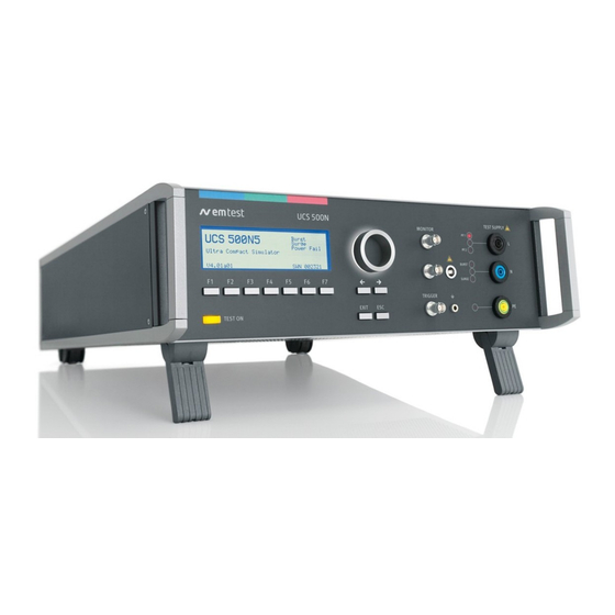
Page 10: Operating Functions
EM TEST UCS 500 Series Operating Functions 3.1. Front view 11 HV pulse Burst output 50 Display Exit Function keys "F1..F7 Escape 12 Ground reference "Test On" CRO U (surge) 13 Coupling (Burst, Surge and EFT) Knob (Inc. / Dec CRO I (surge) 14 Channel PF1 and PF2 10 CRO Trigger output ... - Page 11 EM TEST UCS 500 Series 11 HV pulse Burst output 50 Display Exit Function keys "F1..F7 Escape 12 Ground reference "Test On" CRO U (surge) 13 Coupling (Burst, Surge and EFT) Knob (Inc. / Dec CRO I (surge) 14 Channel PF1 and PF2 10 CRO Trigger output ...
-
Page 12: Rear View
EM TEST UCS 500 Series 3.2. Rear view 1 Test supply input; channel PF1 together with 3 Test supply input neutral the red lamp for phase indication 4 Test supply input PE 2 Test supply input; channel PF2 together with 5 Sync input the red lamp for phase indication Test supply PF1... - Page 13 EM TEST UCS 500 Series 6 Reference Earth connection 10 Warning lamp 7 HV output for Surge pulse 11 External trigger 8 Common output for Surge pulse 12 BNC connector MON U 9 Ventilation 13 BNC connector MON I Reference earth connection The generator has to be connected to the reference earth plane of the test set up.
- Page 14 EM TEST UCS 500 Series 14 Control output 0-10V 19 Serial interface USB 15 Security circuit 20 Parallel interface IEEE 16 Mains selector 115V / 230V 21 Remote control connector 17 Power on switch 22 FAIL 1 18 Fuse of the high voltage power supply 23 FAIL 2 14 Control output 0-10V The voltage is used to control external power sources.
-
Page 15: Operation
EM TEST UCS 500 Series Operation 4.1. Description of the menus The simulator is operated by an easy menu control system. Seven function keys are available to select parameters and functions. All functions are indicated on the display; max. 8 lines and 40 characters. The selected parameter is blinking and can be changed by turning the knob (inc./dec.). -
Page 16: Main Menu
EM TEST UCS 500 Series 4.3. Main Menu MAIN MENU F1 : Burst IEC 61000-4-4 F2 : Surge IEC 61000-4-5/9 F3 : Power Fail IEC 61000-4-11/8/29 F4 : Ringwave IEC 61000-12 F5 : TSurge F7 : Service F1 Burst test With function key F1 the user can select Burst Test as per IEC 61000-4-4. -
Page 17: Service
EM TEST GmbH are shown. The addresses of all EM TEST sales agencies are listed on the web site of EM Test under : www.emtest.com F3 Set-up The software will clearly explain the set-up procedure. F4 Change standard levels The stored standard test levels can be changed within this menu. - Page 18 EM TEST UCS 500 Series F7 Status Status information of the equipment. UCS500N5 UCS500N7 Page 1 UCS500N5 Built in Model Burst Ringwave V5.00 Modules Version Surge Int. 1Ph 005000 SW Number Power Fail Operating DI-Status 0000 Information of Status information 00000035.53 hrs SCR-Status 0000...
-
Page 19: Setup
EM TEST UCS 500 Series 4.5. Setup Firmware V 6.01ax (UCS 500N5) V9.04ax (N7x) SETUP SETUP F1 : Change language / Sprache ändern F1 : Change language / Sprache ändern F2 : LCD backlighting F2 : LCD backlighting F3 : Interfaces F3 : Interfaces F4 : Beep F4 : Beep... - Page 20 EM TEST UCS 500 Series F7 Magnetic field correction factors Af A/m F1: Coil factor Range [0.200...9.99 step 0.01 ] Tf A/V F2: Transformer factor Range [0.020...9.999 step 0.001 ] If A/V F3: Impedance factor Range [0.200...1.00 step 0.01 ] These values are delivered together with the necessary options to conducted magnetic field testing.
-
Page 21: Setup Procedure For Set Voltage
EM TEST UCS 500 Series 4.6. Setup procedure for Set voltage The UCS 500 is able to control an external voltage source with a 0-10V analogue dc signal. The 10V level corresponds to the max. output voltage of the connected voltage source. For the correct setting it is necessary to know the max. -
Page 22: Test Equipment Ucs 500N
EM TEST UCS 500 Series Test Equipment UCS 500N The simulator UCS 500N is separated in different main parts. The control unit is screened to all other parts. 5.1. UCS 500 N5 Back panel Front panel Control unit 1 Power supply board 5 Filter board / connecting board 2 Interface board 6 Keyboard / LCD- display... -
Page 23: Ucs 500 N7
EM TEST UCS 500 Series 5.2. UCS 500 N7 Rearpanel Frontpanel Control unit 1 Power supply board 6 Keyboard / LCD- display 2 Interface board 7 Measuring and control outputs 3 Controller board 8 General power supply input, filter 4 Power supply transformer 9 Ventilation 5 Filter board / connecting board High voltage unit... -
Page 24: Technical Data
EM TEST UCS 500 Series Technical data 6.1. EFT Electrical Fast Transients Burst as per IEC 61000-4-4 Test Level Model N5 Model N7 200V – 5500V ± 10% Step 50V Open circuit * 200V - 5500V ± 10% Step 20V 100V –... -
Page 25: Surge Immunity Requirements As Per Iec 61000-4-5
EM TEST UCS 500 Series 6.2. SURGE Immunity requirements as per IEC 61000-4-5 Test Level Model N5 Model N7 160 V – 5000 V ± 10% Step 20 V 250 V – 7000 V ± 10% Step 50 V Open circuit voltage 80 A –... -
Page 26: Power Fail Generator As Per Iec 61000-4-11
EM TEST UCS 500 Series 6.3. Power Fail Generator as per IEC 61000-4-11 EUT supply Model N5 Model N7 Channel PF1 and PF2 AC voltage/current max. 300V/16A max. 300V/16A Mains frequency 50/60 Hz DC voltage/current max. 300V/16A max. 300V/16A Inrush current more than 500A Protection Electronic fuse for continuous overcurrent / inrush currents... -
Page 27: Ringwave Immunity Requirements As Per Iec 61000-4-12
EM TEST UCS 500 Series 6.4. RINGWAVE Immunity requirements as per IEC 61000-4-12 The Ringwave module is available for the UCS500 N7 generator. Test level Open circuit voltage 6000 V ± 10 % Wave shape voltage Rise time first peak T1 0,5 µs ±... -
Page 28: Telecom Surge Generator As Per Iec 61000-4-5 (Tsurge Module)
EM TEST UCS 500 Series 6.5. Telecom Surge Generator as per IEC 61000-4-5 (TSurge module) UCS 500N5T (includes TSurge module) TSurge7 (external) As per ITU and ETS recommendations 160V – 5’000V 10% 250V – 7’000V 10% Output voltage open circuit Pulse 10/700s 10s ... -
Page 29: Eut Supply Specifications
EM TEST UCS 500 Series 6.6. EUT Supply Specifications Standard models Model Remarks UCS 500N5 300V 16A 1- ph DC 300V / 16A UCS 500N5.1 300V 32A 1- ph DC 300V / 32A UCS 500N7 300V 16A 1- ph DC 300V / 16A ANSI UCS 500N7.1 300V 32A 1- ph... -
Page 30: General Specifications
EM TEST UCS 500 Series 6.7. General Specifications Mains supply 230V/115V, 50/60Hz Power consumption 110W Fuse 230V : 2 AT slow blow 115V : 4 AT slow blow Safety Safety circuit External interlock capability Warning lamp voltage free contact max. 250V 5A Design per IEC 1010, EN 61010 Interfaces... -
Page 31: Technical Data Of Special Generators
EM TEST UCS 500 Series 6.9. Technical data of special generators This chapter describes differing technical data from special generators 6.9.1. UCS 500N5.2T Module Built in modules Surge, T-Surge internal 1ph 16 A AC/DC EUT: Single Phase 300V 16 A Dimensions and weight Dimension 445 x 500 x 420 mm... -
Page 32: Ucs 500N5.5 And Ucs 500N5.6 And Ucs 500N5.9 For Railways Application
EM TEST UCS 500 Series 6.9.2. UCS 500N5.5 and UCS 500N5.6 and UCS 500N5.9 for Railways application Standards: EN 50121-3-2: 2015 EN 50121-4: 2015 EN 50121-5: 2015 Module : Burst Surge UCS 500N5.5: 300V 32A UCS 500N5.6: 300V 32A UCS 500N5.9: 300V 16A Module UCS 500N5.5: Burst, Surge... -
Page 33: Ucs 500N5.11
EM TEST UCS 500 Series 6.9.3. UCS 500N5.11 Module : Burst Surge TSurge ( optional) EUT: 690V 16A Module Available Module Burst, Surge, TSurge Surge coupling L - N, L - PE, N - PE, L + N - PE Dimensions and weight Dimension 445 x 500 x 420 mm... -
Page 34: Ucs 500N6.5
EM TEST UCS 500 Series 6.9.4. UCS 500N6.5 Module : Surge Ring wave External CNV503B7 6kV 32A EUT: Three Phase 3x440V 32A Module Built in modules Surge, Ringwave, TSurge Coupling external CNV503B7 and TSurge Dimensions and weight Dimension 450 x 550 x 285 mm Weight 26.0kg (UCS500N6.5) 38.0kg ( CNV503B7) -
Page 35: Ucs 500N7.1
EM TEST UCS 500 Series 6.9.6. UCS 500N7.1 Modules : Surge Power Fail T-Surge (option) EUT: Single Phase 300V 32A Module Built in modules EFT, Surge, Power Fail Optional module T-Surge Remark Ringwave not possible Dimensions and weight Dimension 445 x 500 x 420mm Weight approx. -
Page 36: Maintenance Setup And Service
EM TEST UCS 500 Series Maintenance setup and service 7.1. General The generator is absolutely maintenance-free by using a solid state semiconductor switch to generate transients 7.2. Test set- up When setting up the test national and international regulations regarding human safety have to be guaranteed. It is recommended to connect the simulator to the ground reference plane of the test set-up. -
Page 37: Calibration And Verification
EM TEST UCS 500 Series 7.5. Calibration and verification 7.5.1. Factory calibration Every EM TEST generator is entirely checked and calibrated as per international standard regulations before delivery. A calibration certificate is issued and delivered along with a list of the equipment used for the calibration proving the traceability of the measuring equipment. -
Page 38: Delivery Groups
EM TEST UCS 500 Series Delivery Groups 8.1. Basic equipment Generator type UCS 500N5 with recommended modules ( Burst, Surge, Power Fail, TSurge) UCS 500N7 with recommended modules ( Burst, Surge, Power Fail, TSurge, Ringwave) Mains cable Mains cable for the EUT supply ... - Page 39 EM TEST UCS 500 Series Surge Coupling/decoupling network as per IEC 61000-4-5 for signal lines type CNV 504/508 (4 wires and 8 wires) 3 phase CNV 503 up to 100A TSurge 7 TSurge module Power Fail V4780 transformer with taps –...
-
Page 40: Eft Burst As Per Iec 61000-4-4
EM TEST UCS 500 Series EFT Burst as per IEC 61000-4-4 Burst Module 5/50ns If the user reduces the test voltage in Quick Start or in the Manual Standard Test Routine, the storage capacitor will be discharged only by the burst pulses. The result is a higher test voltage on the EUT than indicated on the display until the storage capacitor is discharged to the preselected value. -
Page 41: Quick Start
EM TEST UCS 500 Series 9.1.1. Quick Start Easy and very fast operation of all standard functions of the equipment. The latest simulator settings are stored automatically and will be recalled when Quick Start is next selected. Burst Quick start 500V 5kHz 15ms... -
Page 42: Standard Test Routines
EM TEST UCS 500 Series 9.1.2. Standard test routines The user can select preprogrammed standard test routines. Page 2 Burst Standard test routines F1 : IEC 61000-4-4 Level 1 500V F2 : IEC 61000-4-4 Level 2 1000V F3 : IEC 61000-4-4 Level 3 2000V F4 : IEC 61000-4-4... -
Page 43: User Test Routines
EM TEST UCS 500 Series 9.1.3. User Test Routines The user can program, save and recall his own specific test routines. The next pages shows the selection of the functions. USER TEST ROUTINES F1 : Synchronized F2 : Random burst release F3 : Voltage change after T by F4 : Frequency sweep in one single burst F5 : Frequency sweep with constant pulse numbers... - Page 44 EM TEST UCS 500 Series Frequency sweep in one single burst >= 100 ms During one single burst the frequency sweeps from f1 to f2. <= For this function the following limitations have to be >= 5.0 ms respected: >= 5 / f1 tr.
-
Page 45: Burst Generation
EM TEST UCS 500 Series 9.2. Burst generation Discharge switch: The discharge switch is a highly reproducible semiconductor switch. Spike frequencies up to 1000kHz are by a factor of 10 higher than recommended in the actual EFT standards. This means of course that also the pulse energy would be 10 times higher. -
Page 46: Coupling/Decoupling Network
EM TEST UCS 500 Series 9.4. Coupling/decoupling network The decoupling part of the coupling network has to: - filter the interference pulses in the direction to the power supply; - protect other systems that are connected to the same power supply and - realize a high impedance of the power supply, e.g. -
Page 47: Test Setup With Capacitive Coupling Clamp
EM TEST UCS 500 Series - The test generator and the coupling network should be connected to the reference ground plane (acc. to high frequency requirements). - The equipment under test must be isolated from the reference ground plane. The distance should be 10cm. Being part of the EUT, these requirements are also recommended for all connected cables. -
Page 48: Surge Immunity As Per Iec 61000-4-5
EM TEST UCS 500 Series Surge Immunity as per IEC 61000-4-5 Surge Module 1.2/50s – 8/20s The internal coupling network is designed for mains frequency 50Hz / 60Hz. When L – N coupling is selected an additional current of approx. 1.5A flows, caused by the 18F coupling capacitor and the pulse forming network. -
Page 49: Quickstart
EM TEST UCS 500 Series 10.1.1. Quick Start Easy and very fast operation of all standard functions of the equipment. The latest simulator settings are stored automatically and will be recalled when Quick Start is next selected. Surge Quickstart = 2000V L + N - PE = 10s Auto... -
Page 50: Standard Test Routine
EM TEST UCS 500 Series 10.1.2. Standard test Routine Page 2 Standard test routines With the selection of F1 ..F6 the test is conducted F1 : IEC 61000-4-5 Level 1 500V automatically with the parameters and the test sequence F2 : IEC 61000-4-5 Level 2 1000V as required per IEC 61000-4-5. - Page 51 EM TEST UCS 500 Series Standard Test Routines Page 3 (show parameters) Surge Generic EN 61000-4-5 AUTO 10 Pulse + 1000V L-PE 90grd Counter U=970V 000002 STOP STEP I = 010A 000034 - The counter shows the number of triggered pulses per actual test level as well as the number of all triggered test pulses within the running test sequence.
-
Page 52: User Test Routines
EM TEST UCS 500 Series 10.1.3. User Test Routines The user can program, save and recall his own specific test routines. The next pages shows the selection of the functions. User Test Routines F1 : Change polarity after n pulses F2 : Voltage change after n pulses by V F3 : Change the phase angle after n pulses by a F4 : IEC coupling after n pulses... - Page 53 EM TEST UCS 500 Series IEC coupling after n pulses The coupling mode will automatically be changed after the preselected number of pulses has been released. All possible coupling modes will be selected. . The same parameters as under Quick Start can be selected. ANSI A coupling after n pulses The coupling mode with 12Ω...
-
Page 54: Phase Synchronization In 3-Phase System
EM TEST UCS 500 Series 10.1.4. Phase synchronization in 3-phase system Device Firmware versions From V 4.41 to V 4.99 and from V 5.00 and higher UCS 500N5 UCS 500N7 From V 7.43 to V 7.99 and from V 8.03 and higher The built in hardware phase synchronization is between the sync input and PE. - Page 55 EM TEST UCS 500 Series Device Firmware versions UCS 500N5 Up to V 4.40 Up to V 7.42 and from V 8.00 to V 8.02 UCS 500N7 The built in hardware phase synchronization is between the sync input and PE. The user must connect the synchronize line with the sync plug.
-
Page 56: Pulsed Magnetic Field As Per Iec 61000-4-9
EM TEST UCS 500 Series 10.1.5. Pulsed magnetic field as per IEC 61000-4-9 Page 2 (Select function) Surge Magnetic field IEC 61000-4-9 F1 : Quick Start F2 : Magnetic field as per IEC 61000-4-9 F7 : Setup magnetic field The operation of the pulse magnetic field test is similar as to the standard surge routines. Page 2 (show parameter) QUICKSTART 300A/m... -
Page 57: Setup Current Limiter For Surge Current
EM TEST UCS 500 Series 10.1.6. Setup current limiter for surge current The current limiter stops the test run when during a test the measured peak current of a surge pulse is higher than the preselected current value. This safety function protect the EUT for further surge pulses can occur any dangerous situation. -
Page 58: Charging Time For Surge
EM TEST UCS 500 Series 10.1.7. Charging time for surge The energy for charging the surge generator depends on the charging voltage of the internal capacitor of 11uF therefore the following minimum charging time is requested: Operating Manual V 5.40 58 / 99... -
Page 59: Surge Pulse Generation
EM TEST UCS 500 Series 10.2. Surge pulse generation Discharge switch: The discharge switch is a highly reproducible semiconductor switch. 10.3. Coupling/decoupling network The coupling network has to couple the interference pulses to the lines of a power supply system (AC or DC). Capacitive coupling is the specified coupling mode for surge testing. -
Page 60: Coupling To I / O Lines
EM TEST UCS 500 Series 10.3.2. Coupling to I / O lines The coupling to I/O lines is generally realized with other coupling networks than for power supply lines. The loading of the I/O lines with big coupling capacitors is mostly not possible. -
Page 61: Voltage Dips As Per Iec 61000-4-11
EM TEST UCS 500 Series Voltage Dips as per IEC 61000-4-11 Dips Module for voltage Dips and short interruptions. 11.1. Test setup for DIPS and Interruption tests Voltage DIPS For voltage DIPS a connection must be made from the PF2 UCS input to the motorvariac PF2 or V4780, where the reduced voltage is present. -
Page 62: Quick Start
EM TEST UCS 500 Series 11.2.1. Quick Start Easy and very fast operation of all standard functions of the equipment. The latest simulator settings are stored automatically and will be recalled when Quick Start is next selected. Power Fail Quickstart 0dgr 10.00ms U... -
Page 63: Standard Test Routines
EM TEST UCS 500 Series 11.2.2. Standard Test Routines Standard test routines F1 : IEC 61000-4-11 (ac power supply mains) F2 : IEC 61000-4-29 (dc power supply systems) F3 : EN 61000-6-1 Generic standard F4 : EN 61000-6-2 Generic standard F7 : Manual test routine 11.2.2.1. - Page 64 EM TEST UCS 500 Series F7: Voltage Variation Page 4 ( Show parameter) Power Fail IEC 61000-4-11 Variation V2% = = 0 dgr 20ms = 10s = 0.5s Counter START / STOP 000002 Attention: This is the Voltage Variation function which is required in the IEC 61000-4-11:2004. The Voltage Variation function which is conform with the previous IEC 61000-4-11 version is available in the USER TEST ROUTINES.
- Page 65 EM TEST UCS 500 Series 11.2.2.2. F1: IEC 61000-4-29 ( DC power supply mains ) Page 3 Power Fail IEC 61000-4-29 Level 1 10.0 ms Level 2 30.0 ms Level 3 100 ms Level 4 300 ms Level 5 1000 ms F1 ...
- Page 66 EM TEST UCS 500 Series 11.2.2.4. F7: Manual test routine In this menu the user can easy change the parameter online during the test. Page 4 (Show parameter) Power Fail standard routine IEC 61000-4-11 <- -> Level 4 500Ns 0 grd START oV2/td Example:...
-
Page 67: User Test Routines
EM TEST UCS 500 Series 11.2.3. User Test Routines Page 2 (Selection) Power Fail User test routines F1 : Voltage variation as per IEC 61000-4-11 F2 : Change angle after n events by dA F3 : Change duration after n events by dA F4 : Inverse mode F1 Voltage variation as per IEC 61000-4-11 An external power source or motor driven variac is controlled... -
Page 68: The Power Fail Test
EM TEST UCS 500 Series 11.3. The Power Fail Test The power fail simulator operates in the following mode: PF1: The voltage supply at channel PF1 will be interrupted for the preselected time T1. PF2: The voltage supply at channel PF2 will be interrupted for the preselected time T1. U: Channels PF1 and PF2 are supplied with different voltages;... -
Page 69: Overcurrent
EM TEST UCS 500 Series 11.4. Overcurrent Power switches The power switches are electronically protected against overload and short- circuits. The nominal current of the switches is 25A. Special protection requirements of the EUT must be separately assured by the user. -
Page 70: The Power Fail Test
EM TEST UCS 500 Series 11.5. The Power Fail Test The generator type UCS 500N5/N7 simulates the following interference : - Voltage dips - Voltage interruptions - Voltage variations - Inverse 11.5.1. Voltage Interruptions Depending on the preselected test parameters at the front panel of the simulator the power supply for the EUT is interrupted for a certain time and at a certain phase angle (AC power supplies). -
Page 71: Voltage Dips, Voltage Variations
EM TEST UCS 500 Series 11.5.2. Voltage dips, voltage variations Depending on the preselected test parameters, the test voltage is changed to a higher or to a lower value for a certain duration and at a certain phase angle. Voltage variations are normally related to the nominal value of the supply voltage. Therefore two different variacs shall be connected at the rear side of the simulator. -
Page 72: Test Setup And Accessories
EM TEST UCS 500 Series 11.7. Test setup and accessories 11.7.1. Transformer type V4780 The transformer shall be used to generate under-voltages in ac power supply systems. According to the IEC 61000- 4-11 and the EN 50081-2 voltage dips shall be generated as shown in fig. below. Different test levels are recommended 11.7.1.1. - Page 73 EM TEST UCS 500 Series 11.7.1.4. Technical Data V4780 Design Tapped auto-transformer with 40% , 70%, 80%, 100 % output voltage Input: Voltage Uin: max. 250V Frequency 50/60Hz Tap selection manually ( V4780 ) banana plugs for 40%, 70%, 80% Remote control 0.10V dc ( V4780 S2) for 40%, 70%, 80% Output:...
-
Page 74: Motor Variac Type Mv 2616
EM TEST UCS 500 Series 11.7.2. Motor variac type MV 2616 The motor variac can be used to simulate power supply failures as under-voltages, voltage interruptions and voltage variations. The basic standard IEC 61000-4-11 and the generic standard EN 50081-2 are specifying these phenomena. - Page 75 EM TEST UCS 500 Series 11.7.2.3. Technical data MV 2616 Input: Voltage Vin: max. 250V Frequency 50/60Hz Output Voltage Vout: 0 - 260V for channel PF2 additionally Vout=Vin for channel PF1 Current max: 16A Power 0 - 4.1 kVA Control Main switch On/Off for the output voltages Control voltage...
-
Page 76: 50/60Hz Magnetic Field As Per Iec 61000-4-8
EM TEST UCS 500 Series 11.8. 50/60Hz Magnetic Field as per IEC 61000-4-8 Magnetic field standard routine IEC 61000-4-8 <- -> 5 A/m 01:00 min START O H/T With the inc knob the values for the magnetic field strength and test duration can be changed. The actual parameter is indicated by a blinking circle. - Page 77 EM TEST UCS 500 Series Test setup with MC 26100 for H-Fields up to 1000A/m Schematics Test setup Schematics and Test setup with UCS500Nx, MV 2616, MC 26100 and MS 100N Option for required magnetic field tests as per IEC 61000-4-8 - External motor variac MV 2616 - External Magnetic field antenna MS 100N - External current transformer MC 26100 to test 100 to 1000A/m levels...
-
Page 78: Ringwave Immunity As Per Iec 61000-4-12
EM TEST UCS 500 Series Ringwave Immunity as per IEC 61000-4-12 Ringwave Module 0.5s – 100kHz 12.1. Operation The menu offers different test routines for ring wave testing. Ring wave F1 : Quick Start F1 Quick Start Easy and fast online-operation of the equipment. 12.1.1. - Page 79 EM TEST UCS 500 Series Page 3 (CHANGE) Ring wave Quick start Voltage 250V 6000V angle 0dgr 360dgr Events 30000 Repetition Rep : 999s 12 Ohm L+N+PE Note: At polarity setting ALT it is necessary to double the number of impulses. Example n=2 => one impulse positive and one impulse negative.
-
Page 80: Ring Wave Pulse Generation
EM TEST UCS 500 Series 12.2. Ring wave pulse generation Discharge switch: The discharge switch is a highly reproducible semiconductor switch. 12.3. Coupling/decoupling network The coupling network has to couple the interference pulses to the lines of a power supply system (AC or DC). Capacitive coupling is the specified coupling mode for surge testing. -
Page 81: Telecom Surge
EM TEST UCS 500 Series Telecom Surge For Telecom pulses there are the following extensions modules: TSurge5 with built in module to the UCS500N5T that will be boosted up to 6HU. TSurge7 as an additional module to the UCS500N7 13.1. -
Page 82: Tsurge Menu
EM TEST UCS 500 Series 13.4. TSurge Menu TSurge test are possible in the menu TSurge Quickstart. This menu is only available if the CTRL cable between TSurge7 module and UCS500N7 is connected and the TSurge is detected by the UCS500N7. The menu offers different test routines for ring wave testing. -
Page 83: Coupling Network
EM TEST UCS 500 Series 13.5. Coupling Network The coupling network is responsible to couple the test pulse to the lines ( ac or dc or signal lines ) using single coupling resistors inside the TSurge module. The Telecom surge is generated and coupled to the EUT as shown in the next figure. The charging rectifier charges the both 10F and 9F capacitor banks in the UCS500N7 and TSurge module Depend of the polarity the pulse forming network will be charged. -
Page 84: Test Setup
EM TEST UCS 500 Series 13.6. Test Setup Setup The TSurge6.1 must be placed on the top of the UCS 500N7 generator. Cabling UCS500N7 – TSurge7 1. Earth cable UCS500N7 – TSurge7 HV and COM cable Charging cables + / - UCS500N7 – TSurge7 UCS500N7 –... -
Page 85: Pulse 10 / 700S As Per Iec 61000-4-5
EM TEST UCS 500 Series 13.7.2. Pulse 10 / 700s as per IEC 61000-4-5 Voltage verification Test level : 4000 V (for N5 type max. 5000V; respectively 7000V for N7 Type). Pulse : 10 / 700s open circuit voltage waveshape Output : on 25... -
Page 86: Appendix
EM TEST UCS 500 Series Appendix 14.1. Declaration of CE-Conformity 14.1.1. Declaration of Conformity UCS 500N5 Manufacturer: EM TEST (Switzerland) GmbH Address: Sternenhofstr. 15 CH 4153 Reinach BL1 Switzerland declares, that under is sole responsibility, the product’s listed below, including all their options, are conformity with the applicable CE directives listed below using the relevant section of the following EC standards and other normative documents. -
Page 87: Declaration Of Conformity Ucs 500N7
EM TEST UCS 500 Series 14.1.2. Declaration of Conformity UCS 500N7 Manufacturer : EM TEST (Switzerland) GmbH Address: Sternenhofstr. 15 CH 4153 Reinach BL1 Switzerland declares, that under is sole responsibility, the product’s listed below, including all their options, are conformity with the applicable CE directives listed below using the relevant section of the following EC standards and other normative documents. -
Page 88: Declaration Of Conformity Ucs 500N5X Models For One Phenomenon
EM TEST UCS 500 Series 14.1.3. Declaration of Conformity UCS 500N5x models for one phenomenon Manufacturer : EM TEST (Switzerland) GmbH Address: Sternenhofstr. 15 CH 4153 Reinach BL1 Switzerland declares, that under is sole responsibility, the product’s listed below, including all their options, are conformity with the applicable CE directives listed below using the relevant section of the following EC standards and other normative documents. -
Page 89: Declaration Of Conformity Ucs 500N5X Models
EM TEST UCS 500 Series 14.1.4. Declaration of Conformity UCS 500N5x models Manufacturer : EM TEST (Switzerland) GmbH Address: Sternenhofstr. 15 CH 4153 Reinach BL1 Switzerland declares, that under is sole responsibility, the product’s listed below, including all their options, are conformity with the applicable CE directives listed below using the relevant section of the following EC standards and other normative documents. -
Page 90: Declaration Of Conformity Tsurge 7 Module For Ucs 500N7
EM TEST UCS 500 Series 14.1.5. Declaration of Conformity TSurge 7 Module for UCS 500N7 Manufacturer : EM TEST (Switzerland) GmbH Address: Sternenhofstr. 15 CH 4153 Reinach BL1 Switzerland declares, that under is sole responsibility, the product’s listed below, including all their options, are conformity with the applicable CE directives listed below using the relevant section of the following EC standards and other normative documents. -
Page 91: Declaration Of Conformity Cnt 516
EM TEST UCS 500 Series 14.1.6. Declaration of Conformity CNT 516 Manufacturer : EM TEST (Switzerland) GmbH Address: Sternenhofstr. 15 CH 4153 Reinach BL1 Switzerland declares, that under is sole responsibility, the product’s listed below, including all their options, are conformity with the applicable CE directives listed below using the relevant section of the following EC standards and other normative documents. -
Page 92: Declaration Of Conformity Tapped Transformer
EM TEST UCS 500 Series 14.1.7. Declaration of Conformity Tapped Transformer Manufacturer : EM TEST (Switzerland) GmbH Address: Sternenhofstr. 15 CH 4153 Reinach BL1 Switzerland declares, that under is sole responsibility, the product’s listed below, including all their options, are conformity with the applicable CE directives listed below using the relevant section of the following EC standards and other normative documents. -
Page 93: Ucs 500N - General Diagram
EM TEST UCS 500 Series 14.2. UCS 500N - General Diagram 14.3. Main diagram control connection Operating Manual V 5.40 93 / 99... -
Page 94: Main Diagram High Voltage Connection
EM TEST UCS 500 Series 14.4. Main diagram high voltage connection Operating Manual V 5.40 94 / 99... -
Page 95: Cnt 508N
EM TEST UCS 500 Series 14.5. CNT 508N The CNT 508N is a coupling network for coupling surge pulses to 8 lines via a 25 resistor. Depends from where the pulse is adapted different waveshapes can be applied to the EUT. 14.5.1. - Page 96 EM TEST UCS 500 Series 14.5.3. Main diagram 14.5.4. Test Setup 14.5.5. Accessories: Screw set Earth cable HV cable COM cable 8 (red) + 2 (black) EUT cables 2m Operating Manual V 5.40 96 / 99...
-
Page 97: Cnt 516
EM TEST UCS 500 Series 14.6. CNT 516 The CNT 516 is a coupling network for coupling surge pulses to 16 lines via a 25 resistor. Depends from where the pulse is adapted different waveshapes can be applied to the EUT. 14.6.1. - Page 98 EM TEST UCS 500 Series 14.6.3. Main diagram 14.6.4. Test Setup 14.6.5. Accessories: Screw set Earth cable HV cable COM cable 16 (red) + 3 (black) EUT cables 2m Operating Manual V 5.40 98 / 99...
-
Page 99: Usb Interface
EM TEST UCS 500 Series 14.7. USB interface USB interface “USB B” connector. For data transfer a USB interface is available. The internal RS 232 interface is converted to USB standard. Therefore, the user must set the same baud rate in the device and control software.
Need help?
Do you have a question about the UCS 500Nx Series and is the answer not in the manual?
Questions and answers