Table of Contents
Advertisement
Quick Links
Advertisement
Table of Contents

Related Manuals for AV Access 4KMX44-H2


Summary of Contents for AV Access 4KMX44-H2
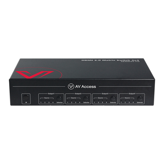
- Page 1 4KMX44-H2 4x4 Matrix with Audio Outputs User Manual...
- Page 2 AV Access Technology Limited assumes no responsibility for any inaccuracies that may be contained in this document. AV Access Technology Limited also makes no commitment to update or to keep current the information contained in this document.
- Page 3 Important Safety Instructions Do not expose this device to rain, moisture, dripping or splashing. No objects filled with liquids, such as vases, shall be placed on the device. Do not install or place this unit in a bookcase, built-in cabinet, or in another ...
-
Page 4: Table Of Contents
Table of Contents Introduction ......................2 Features ............................ 2 Package Contents ........................3 Panel ............................4 Front Panel........................4 Rear Panel ........................4 Installation and Application................. 6 Brackets Installation ......................6 Steps to install the device in a suitable location ..........6 Application .......................... -
Page 5: Introduction
Introduction Introduction Overview 4KMX44-H2 is a 4x4 compact HDMI matrix switcher, specially designed for cost conscious projects and buyers. It features not only basic functions like cross-point switching and control (IR, RS-232, IP), but also advanced functions like auto-downscaling for each HDMI output when it is connected to 1080P display. -
Page 6: Package Contents
Introduction web module). Rich control options, including RS232 control, IR, IP Control and front panel buttons control. Package Contents Before you start the installation of the product, please check the package contents: Matrix x 1 Power Adapter (DC 12V 2A) x 1 ... -
Page 7: Panel
Introduction Panel Front Panel Name Description IR Window Receive IR signals. On: The current HDMI input is selected. Input LED (1-4) Off: The current HDMI input is not selected. Output Selection Click to select input source for Output (1-4) Button (1-4) separately. - Page 8 Introduction Name Description HDMI Out 1-4 Connect to HDMI displays. For firmware upgrade. Connect to a control PC or control system for RS232 RS232 serial control. Connect to local area network or a control system for IP Control telnet or Web UI control. IR Ext.
-
Page 9: Installation And Application
Installation and Application Installation and Application Brackets Installation Note: Before installation, please ensure the device is disconnected from the power source. Steps to install the device in a suitable location Attach the installation bracket to the enclosure using the screws that were provided in the package separately. -
Page 10: Application
Installation and Application Application Amplifier Router Ethernet Switch Connect audio devices to SPDIF Out (1-4) ports, Connect the Connect for additional SPDIF Out ports can output audio DC 12V control options: RS232 Control, de-embedding power cord IP Control or IR Control. provided. -
Page 11: Ir Remote Control
IR Remote Control IR Remote Control You can switch among multiple inputs for each output display by pointing the matrix IR remote directly at the IR window on the front panel or the IR receiver connected to the rear panel. Steps for IR Remote Operation: Point the matrix IR Remote directly at the IR window on front panel or at the IR receiver connected to the rear panel. - Page 12 IR Remote Control Select previous input Select next input for Output 1 for Output 1 Output 1 Select specific input for Output 1 To cycle through multiple inputs for your target output, press the previous ) or next ( ) button. Virtual IR Code Supported by Default (Matrix Switching Code): Code IN 3...
-
Page 13: Rs232 Control
RS232 Control RS232 Control Advanced users may need to control the matrix through RS232 serial communication. Connect a control PC or control system to the RS232 port of the receiver. API command for RS232 control is available in the separate document “API Command Set_4KMX44-H2”. -
Page 14: Web Ui Control
Web UI Control Web UI Control The Web UI designed for the matrix is available for switching control, general and advanced settings. The Web UI is accessible through a browser with latest version, e.g. Chrome, Firefox, Safari, Opera, IE10+, etc. Access the Web Interface Connect the IP Control port of the matrix to the Ethernet switch, and connect your PC to the same network. -
Page 15: General
Web UI Control General The General Page includes: Switch, EDID, EDID Read, CEC, Audio Mute, HDCP, Preset. Switch The Switch section manages distribution of input sources to output displays. By default, Input 1 corresponds to Output 1, Input 2 corresponds to Output 2, Input (n) corresponds to Output (n), n = 1, 2, 3, 4. - Page 16 Web UI Control EDID Read Click “Enter” to open the EDID Setting page. Select Port: Click from the drop-down menu to choose an Output port (1-4) for EDID setting. Read: Click to read the EDID of the Output port you choose. ...
- Page 17 Web UI Control Output Port: Select one Output (1-4) port or all from the drop-down menu to control. Note: When Output port is set to “all”, the Auto CEC and Delay Time (min) settings are disabled. Manual (ON/OFF): Click “ON/OFF” button to power on/off the CEC-enabled ...
-
Page 18: Advanced
Web UI Control HDCP HDCP Support allows you to enable or disable HDCP compatibility of each input. By default, HDCP Support is switched ON at each input and content protected by HDCP standard will be received. Preset The Preset section saves or loads the Switch settings to or from the matrix. Advanced The Advanced page includes: Network, Login Password, Custom Web UI Logo, WEB Firmware Upgrade, ARM Firmware Upgrade, MCU Firmware Upgrade, System,... - Page 19 Web UI Control by the DHCP server connected. Static: When enabled, set up the IP address manually. Apply: Click to enable the network setting. The default setting is DHCP. Note: When “Static” is selected, please ensure your PC is in the same network ...
- Page 20 Web UI Control To create customized Web UI logo: Click “Browse” button to browse the LOGO file. Click “Apply”, the following window will appear. Click "here" to reconnect the system. When completed, the new logo will appear on the upper left corner of the screen.
- Page 21 Web UI Control completed. Please wait for about 3 minutes and then refresh and log in again. Note: DO NOT power off the device when upgrading. MCU Firmware Upgrade Click “Browse” for the update bin file. Click "Upgrade" to start the MCU Firmware upgrade. The matrix will upgrade and reboot automatically when upgrading MCU is completed.
- Page 22 Web UI Control Note: Please wait about 30 seconds to reaccess Web UI by refreshing the browser. To reboot the device: Click the “Reboot” icon, the following window will be popped up, click “Ok” to reboot the device. Note: Please wait about 30 seconds to reaccess Web UI by refreshing the browser. Firmware Version This section allows you to obtain information of the current firmware in use.
-
Page 23: Specifications
Specifications Specifications Technical 4 x HDMI In, 4 x HDMI Out, 1 x RS232, Input/Output Port 1 x IP Control (RJ45), 4 x SPDIF Out (Digital), 1 x FW (Micro USB), 1 x DC 12V IN HDMI with 4K@60Hz 4:4:4, HDR 10, HLG & Dolby Vision, HDCP 2.2 Input/Output Signal Type Note: Dolby vision is not supported in downscaler... - Page 24 Specifications General Operating Temperature 0°C to 45°C (32°F to 113°F) Storage Temperature -20°C to 70°C (-4°F to 158°F) Humidity 10% to 90%, non-condensing Human-body Model: ESD Protection ±8kV (Air-gap discharge)/ ±4kV (Contact discharge) Power Supply DC 12V 2A Power Consumption (Max) 10.8W Device Dimension 215mm x 42mm x 120.2mm/8.46”...
-
Page 25: Trouble Shooting
Trouble Shooting Trouble Shooting Steps of Regular Troubleshooting Routine Power: Please make sure all devices are powered on. (source, matrix, display devices) Indicator: Please make sure LED indicators of the device are normal according to user manual. Devices: Please make sure picture can be shown normally when connecting source to display devices directly. -
Page 26: Warranty
The warranty has expired. The defects are caused by the fact that the product is repaired, dismantled or altered by anyone that is not from an AV Access Technology Limited authorized service partner. The defects are caused by the fact that the product is used or handled improperly, roughly or not as instructed in the applicable User Guide. - Page 28 AV Access Technology Limited V1.0.0...
Need help?
Do you have a question about the 4KMX44-H2 and is the answer not in the manual?
Questions and answers