Advertisement
Quick Links
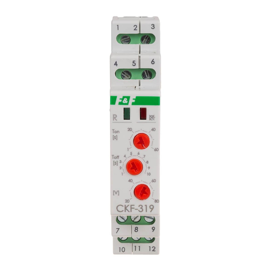
CKF-319 TRMS
Phase loss and phase
sequence sensor
Do not dispose of this device in the trash along with other waste!
According to the Law on Waste, electro coming from households free of charge and can
give any amount to up to that end point of collec� on, as well as to store the occasion of
the purchase of new equipment (in accordance with the principle of old-for-new, regard-
less of brand). Electro thrown in the trash or abandoned in nature, pose a threat to the
environment and human health.
Purpose
The CKF-319 phase loss and phase sequence microprocessor
sensor without neutral wire is designed to protect electric motor
powered from the three-phase network in following cases:
» voltage loss in at least one phase;
» voltage drop in at least one phase below 150 V;
» voltage increase in at least one phase above 280 V;
» voltage asymmetry between phases above the set value;
» incorrect phase sequence.
The sensor correctly measures the true rms value of the
voltage (TrueRMS), even when the power supply voltage
is (disturbed) distorted.
F&F Filipowski sp. j.
Konstantynowska 79/81, 95-200 Pabianice, POLAND
phone/fax (+48 42) 215 23 83 / (+48 42) 227 09 71
www.fif.com.pl; e-mail: biuro@fif.com.pl
- 1 -
Advertisement

Related Manuals for F&F CKF-319 TRMS


Summary of Contents for F&F CKF-319 TRMS
- Page 1 Konstantynowska 79/81, 95-200 Pabianice, POLAND phone/fax (+48 42) 215 23 83 / (+48 42) 227 09 71 www.fif.com.pl; e-mail: biuro@fif.com.pl CKF-319 TRMS Phase loss and phase sequence sensor Do not dispose of this device in the trash along with other waste! According to the Law on Waste, electro coming from households free of charge and can give any amount to up to that end point of collec�...
- Page 2 Functioning The correct power supply voltage is indicated by a green LED. Voltage drop below 150 V or increase above 880 V for at least one phase or voltage asymmetry above the set value is signaled by the green LED going off. Both of the above anomalies (exceeding the voltage threshold, asymmetry) cause the relay of the device to be switched off and, as a result, the motor to be disconnected.
-
Page 3: Front Panel
Front panel - 3 -... - Page 4 Signalling Description Correct network parameters, the relay is on Countdown to switch-on or switch-off of the relay (depending on the current state of the output) Asymmetry or exceeding of the voltage threshold. Relay switched off (voltage value of any of the phases below 150 V or above 280 V or asymmetry above the set value)
- Page 5 Voltage waveforms Legend: T1 = 1÷10 s T2 = 1÷60 s - 5 -...
- Page 6 If a voltage drop below 150 V or a rise above 280 V is detected, the relay will be switched off with a delay of 1 s. In this case, both LEDs will will be switched off. If the phase voltages return to normal values, the relay will be switched on after T2 time.
- Page 7 Legend: T2 = 1÷60 s - 7 -...
- Page 8 If the wrong phase rotation sequence is detected at the input terminals of the device, the relay will be switched off immedia- tely. The red LED will be on to indicate a phase sequence error. When the correct phase sequence returns, the relay will be swi- tched on with a delay of T2.
- Page 9 Mounting 1. Check the correct operation of the motor (direction of ro- tation). 2. Disconnect the power supply. 3. Fix the sensor on a rail in the control box. 4. Connect the phases in sequence to terminals 1, 6, 4. To ter- mnial 3 connect N-wire.
- Page 10 Wiring diagram Contacts configuration - 10 -...
- Page 11 The changeover contact of the relay allows to connect a visual or audible signalling system that informs abo- ut the relay activation, which means switching off the motor. Technical data power supply 3×400 V+N contact separated 2×NO/NC maximum load current (AC-1) 2×8 A signaling of correct power supply 2×LED...
-
Page 12: Warranty
Warranty The F&F products are covered by a warranty of the 24 months from the date of purchase. Effective only with proof of purchase. Contact your dealer or directly with us. CE declaration F&F Filipowski sp. j. declares that the device is in conformity with the essential requirements of The Low Voltage Directive (LVD) 2014/35/EU and the Electromagnetic Compatibility (EMC) Directive 2014/30/UE. - Page 13 General work safety conditions » Please read the instructions carefully before installation. » The device should be installed and operated by qualified per- sonnel who are familiar with its design, operation, and asso- ciated risks. » Do not install a sensor that is damaged or incomplete. »...
Need help?
Do you have a question about the CKF-319 TRMS and is the answer not in the manual?
Questions and answers