
Related Manuals for VWR International 1410


Summary of Contents for VWR International 1410
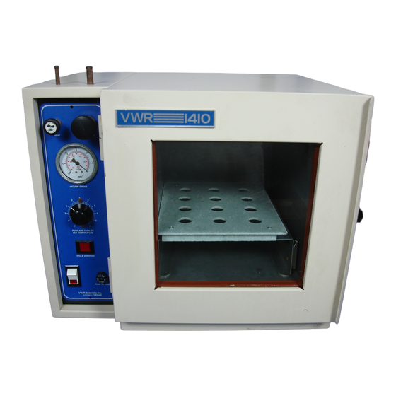
- Page 1 VACUUM OVEN MODEL: 1410,1430 INSTALLATION AND OPERATIONAL MANUAL Sheldon Manufacturing Inc. P.O. Box 627 Cornelius, Oregon 97113 EMAIL: tech@Shellab.com INTERNET: http://www.Shellab.com/~Shellab 1-800-322-4897 (503) 640-3000 FAX (503) 640-1366...
-
Page 2: Table Of Contents
TABLE OF CONTENTS SECTION 1.0 RECEIVING AND INSPECTION SECTION 2.0 GRAPHIC SYMBOLS SECTION 3.0 INSTALLATION SECTION 4.0 CONTROL PANEL OVERVIEW SECTION 5.0 PRECAUTIONS SECTION 6.0 VACUUM OPERATION SECTION 7.0 OPERATION SECTION 8.0 MAINTENANCE SECTION 9.0 TROUBLESHOOTING AND SERVICE SECTION 10.0 PARTS LIST UNIT SPECIFICATIONS SCHEMATICS... -
Page 3: Receiving And Inspection
Section RECEIVING AND INSPECTION Your satisfaction and safety require a complete understanding of this unit. Read the instructions thoroughly and be sure all operators are given adequate training before attempting to put the unit in service. NOTE: This equipment must be used only for its intended application;... -
Page 4: Graphic Symbols
Section GRAPHIC SYMBOLS Your oven has been provided with a display of graphic symbols which should help in identifying the use and function of the available user adjustable components. Indicates "AC Power On". Indicates "I/O" (ON/OFF). Indicates "Vacuum Gauge". Indicates "Vent (Gas)". Indicates "Vacuum". -
Page 5: Installation
Leveling: The unit must sit level and solidly. The Model 1410 has four rubber feet that are already attached to the unit and are not adjustable. Leveling feet are supplied with Model 1430 and must be installed in the four holes in the bottom corners of the unit. - Page 6 corner until the unit stands solid and level. If the unit must be moved, turn the leveling feet in all the way (clockwise) to prevent damage while moving. Cleaning: The oven interior was cleaned at the factory, but not sterilized. Remove all shelving and clean with a disinfectant that is appropriate to your application.
-
Page 8: Control Panel Overview
Section CONTROL PANEL OVERVIEW (See Figure Two) POWER: The main power I/O (ON/OFF) switch must be in the I/On position before any electrical systems are optional. HEATING: This pilot lamp is on when the temperature controller has activated the heating elements to reach and maintain set point. TEMPERATURE CONTROLLER: This is the manually adjustable temperature controller marked SET TEMPERATURE. - Page 9 FIGURE TWO...
-
Page 10: Precautions
Section PRECAUTIONS THIS IS NOT AN EXPLOSION PROOF OVEN. Do not place or use explosive, combustible, or flammable materials in the oven. Do not use sealed containers in the oven chamber. Do not cut or remove the ground prong from the power cord or use an ungrounded 2-prong adapter plug. -
Page 11: Vacuum Operation
A pump with a pumping capacity four times greater than the chamber volume is advisable. For example a 1410 has a chamber volume of one (1) cubic foot so a pump with a pumping capacity of four (4) cubic feet per minute is recommended. -
Page 12: Operation
Section OPERATION NOTE: Slight vapor or smoke may occur in the initial heat-up. This is the dissipation of protective coatings that have been applied to the oven elements. Power Supply: Connect the service cord to a grounded outlet and push the power switch to the I/ON position. -
Page 13: Maintenance
Section MAINTENANCE NOTE: Prior to any maintenance or service on this unit, disconnect the service cord from the power supply. Cleaning: Disinfect the oven interior on a regular basis. To prepare the oven for cleaning remove the shelves and door gasket. The shelves and door gasket are autoclavable. - Page 14 Section TROUBLESHOOTING Always make a visual inspection of the oven and control console when troubleshooting. Look for loose or disconnect wires or tubing, which may be the source of the trouble. The oven is designed so that no internal electrical servicing should be required under normal conditions.
- Page 15 unstable Will not maintain set point 1/ assure that set point is at least 5 degrees over ambient room temperature 2/ see if ambient room temperature is fluctuating MECHANICAL door not sealing 1/ check physical condition of gasket 2/ assure that gasket clamps are in original location 3/ adjust hinge blocks 4/ Confirm that unit has not been damaged and body is not out of square.
- Page 16 proper shipping instructions. To insure prompt handling, the return authorization number should be placed on the outside of the package or container. Make sure a detailed explanation of the reason for return is enclosed with the unit. For information on where to contact customer service, please see the manual cover.
-
Page 17: Parts List
115V 220V Door Gasket, Standard 100029 100029 Silicone - 1410 Door Gasket, Standard 100037 100037 Silicone - 1430 Door Glass - 1410 700027 700027 Door Glass - 1430 110107 110107 Element Assembly - 1410 9570741 9570741 Element Assembly - 1430... -
Page 18: Unit Specifications
UNIT SPECIFICATIONS Weight Shipping 1410 67 lbs. 55 lbs. 1430 170 lbs. 115 lbs. Dimensions Exterior WxDxH Interior WxDxH (in.) (in.) 1410 20.5x17x16.3 9x12x9 1430 23.8x26.3x20.3 12x20x12 Capacity Cubic Feet 1410 1430 Temperature Range Uniformity Sensitivity 1410 Amb.+ 5° to 200°C 2.0°... - Page 19 WIRE DIAGRAM...
- Page 20 SHELDON MANUFACTURING, INC. LIMITED WARRANTY Sheldon Manufacturing, Inc., (“Manufacturer”) warrants for the original user of this product in the U.S.A. only that this product (parts only if outside of the U.S.A.) will be free from defects in material and workmanship for a period of two years from the date of delivery of this product to the original user (the “Warranty Period”).
- Page 21 San Diego, CA Lake Charles, LA S. Plainfield, NJ S A N D I M A S , Or Call Direct for Specialized Service Locations: VWR International Switzerland VWR Furniture Division 3000 Hadley Rd Ruchligstrasse # 20 P.O. Box 3405 S.
Need help?
Do you have a question about the 1410 and is the answer not in the manual?
Questions and answers