Table of Contents
Advertisement
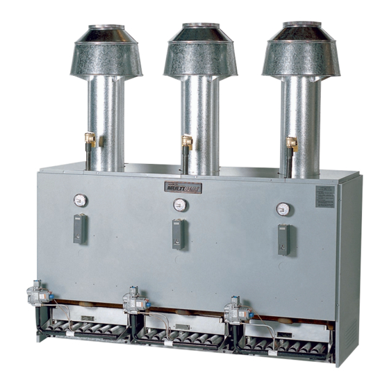
MR SERIES
INSTALLATION
MANUAL AND
REPLACEMENT
PARTS LIST
Modular Gas-Fired Cast
Iron Water Heating Plants
360,000 to 2,400,000
Btuh Input
Applicable For Larger Heating
Plants Using Boiler Banks Of
8-Modules Or Less
SECTION 1: INTRODUCTION
Heating Plant Design............................................2
Code Compliance.................................................2
Heating Plant Shipment........................................2
Heating Plant Dimensions.................................... 3
Step 1: Planning Ahead........................................4
Step 2: Arranging Heating Plant...........................5
Step 3: Setting & Aligning Modules......................5
Step 1: Planning Ahead........................................6
Step 2: MC Heat Exchangers...............................6
Step 3: Supply & Return Headers........................6
Step 4: Hydronic Components..............................7
Step 5 Hydrotesting The Systems........................8
Combination Heat/Cool Systems........................10
Step 1: Planning Ahead......................................11
Step 2: Drafthoods & Vent Dampers...................12
Step 3: Vent Connectors & Slip Joints................13
NOTE: If shop drawings have not been provided, refer to the Appendices at the rear of this manual for sizing
(breeching, chimney & gas piping) and control system data.
IN UNITED STATES: 260 NORTH ELM ST • WESTFIELD, MA 01085 • (413) 564-5515 • FAX (413) 568-9613
IN CANADA: 5211 CREEKBANK ROAD • MISSISSAUGA, ONT. L4W 1R3 • (905) 625-2991 • FAX (905) 625-6610
®
Step 4: Breeching Runs.......................................14
Jacket Assembly..................................................15
Step 1: Gas Main & Gas Headers.......................16
Step 2: Test Gas Piping.......................................16
Module Wiring......................................................17
Step 1: Planning Ahead......................................19
Step 2: Start-Up & Adjustments..........................19
Step 3: How To Change Orifices.........................21
APPENDICES
A: Breeching/Chimney Sizing..............................22
B: Gas Pipe Sizing..............................................24
C: Control Guidelines..........................................26
D: Field Installation of Vent Damper....................31
Replacement Parts List.......................................32
MRC2-1103
42-9154
Advertisement
Table of Contents

Related Manuals for HydroTherm MultiTemp MR Series


Summary of Contents for HydroTherm MultiTemp MR Series
-
Page 1: Table Of Contents
MRC2-1103 42-9154 ® MR SERIES INSTALLATION MANUAL AND REPLACEMENT PARTS LIST Modular Gas-Fired Cast Iron Water Heating Plants 360,000 to 2,400,000 Btuh Input Applicable For Larger Heating Plants Using Boiler Banks Of 8-Modules Or Less SECTION 1: INTRODUCTION Step 4: Breeching Runs........14 Heating Plant Design..........2 Code Compliance..........2 SECTION 5: INSTALLING JACKETS... -
Page 2: Heating Plant Design
This means that more or fewer l’egard des détecteurs de monoxyde de carbone et modules are operated in response to an increase or de- crease in actual heating load. Hydrotherm has develop- observer entretien de manufacturier pour cette chaudiére! ed three basic methods (levels) of control which meet most operating requirements encountered. -
Page 3: Heating Plant Dimensions
and "B" jackets are furnished to form a complete enclo- Optional Heat Exchanger: When ordered, each heat sure for the entire heating plant. exchanger is shipped with the pipe and fittings required for installation. There are three types of heat exchangers Optional Header Sets: When ordered, each header set for volume water heating - “MC2”... -
Page 4: Section 2: Installing Modules
SECTION 2: INSTALLING MODULES STEP 1: PLANNING AHEAD IMPORTANT TO NOTE NOTE: Modules employ atmospheric combustion. Combustion air must not be contaminated with halo- 1. Observe minimum clearances to combustibles. genated hydrocarbon vapors, cleaning fluid vapors, aerosol propellants, freon or other corrosive chemi- 2. -
Page 5: Step 2: Arranging Heating Plant
STEP 2: ARRANGING HEATING PLANT 1. Locate heating plant as close to the chimney as possi- 4. Make sure that any connecting breeching runs will not ble so breeching length to chimney is kept to a minimum. oppose or face each other, but rather mix together in the Only 24”... -
Page 6: Section 3: Installing Water Piping
FIELD-SUPPLIED COMPONENTS: Some of the follow- chemical analysis of your system water. ing components may not have been supplied by Hydrotherm, depending on how the heating plant was CAUTION: Modules are not for use in systems where ordered, but are required for installation: air separator, water is replenished. -
Page 7: Step 4: Hydronic Components
STEP 3: SUPPLY & RETURN HEADERS (CONTINUED) Examples of typical supply & return water piping for headers. RETURN No more than eight RETURN modules may be SUPPLY SUPPLY directly connected! BACK TO BACK MORE THAN 8 MODULES IN-LINE - 8 MODULES OR LESS RETURN SUPPLY IN-LINE - MORE THAN 8 MODULES... -
Page 8: Step 5 Hydrotesting The Systems
STEP 4: HYDRONIC COMPONENTS (CONTINUED) MANUAL RESET HI-LIMIT : Locate in supply piping where it cannot cause isolation of any particular loop or downstream of connection of the last module. zone from the main system. Follow manufacturer’s instal- lation instructions. LOW WATER CUTOFF : (Electronic type or float type) Locate in supply header. - Page 9 TYPICAL PIPING FOR SPACE HEATING SYSTEM FLOW CHECK VALVE CIRCULATOR AIR ELIMINATOR (AIR VENT) City Water Supply SEPARATOR EXPANSION MANUAL RESET TANK HI-LIMIT LOW WATER CUTOFF To Potable Water System BACKFLOW PRESSURE PREVENTER REDUCING (FILL) VALVE SHUT-OFF MAKE-UP WATER METER VALVE BASKET TYPE STRAINER...
-
Page 10: Combination Heat/Cool Systems
TYPICAL PIPING FOR VOLUME WATER HEATING ONLY (INSTANTANEOUS RECOVERY) AIR ELIMINATOR (AIR VENT) THERMOMETER Service Hot Water Supply MIXING VALVE MANUAL RESET SHUT-OFF VALVE HI-LIMIT BRONZE CIRCULATOR FLOW CHECK VALVE Service Recirculating LOW WATER Hot Water CUTOFF BACKFLOW PREVENTER City Water Supply PRESSURE... -
Page 11: Section 4: Venting The Heating Plant
SECTION 4: VENTING THE HEATING PLANT STEP 1: PLANNING AHEAD IMPORTANT TO NOTE: BREECHING CONSTRUCTION REQUIREMENTS: Round breeching is preferred to maximize flue gas flow. 1. Breeching runs must be as short as possible. Rectangular breeching is the only acceptable alterna- tive;... -
Page 12: Step 2: Drafthoods & Vent Dampers
STEP 2: DRAFTHOODS & VENT DAMPERS 1. Install drafthood on each module’s flue outlet. VENT ANGLE DAMPER CONNECTOR DANGER: Drafthood, flue outlet and vent damper as supplied must not be altered in any way as proper module operation would be jeopardized. Flame roll- CABLE out, fire or carbon monoxide poisoning will result. -
Page 13: Step 3: Vent Connectors & Slip Joints
STEP 3: VENT CONNECTORS & SLIP JOINTS 1. Install a vent connector between each module’s draft- 3. Vent connector should connect to the breeching with a hood (or vent damper) outlet and the breeching. Vent straight 90° connection. For improved flue gas flow, vent connector diameter should be the same as drafthood (or connectors may be installed with a 45°... -
Page 14: Step 4: Breeching Runs
STEP 4: BREECHING RUNS FIG. 4.9 FIG. 4.8 TAPERED INCREASER 1. Breeching can be full size for an entire bank of boilers 4. ALL BREECHING RUNS MUST BE PITCHED 1/4” (Figure 4.8 left) or may be tapered (Figure 4.9 right). PER FOOT OF LENGTH UPWARDS TOWARD THE using one tapered division within a bank of eight mod- CHIMNEY. -
Page 15: Section 5: Installing Jackets
SECTION 5: INSTALLING JACKETS NOTE: Remember, “A” jacket sets are for enclosing 3. Install top panels starting with left top panel. Lock two modules and “B” jacket sets are for enclosing each panel into the preceding panel and secure with the three modules. -
Page 16: Section 6: Installing Gas Piping
SECTION 6: INSTALLING GAS PIPING STEP 1: GAS MAIN & GAS HEADERS 1. Gas pipe (gas main and gas headers) must be sized to lowest point in the gas main. The vertical rise of sedi- provide a total maximum pressure drop of 0.3” W.C. (nat- ment trap must be a minimum of three times gas main ural gas) or 0.5”... -
Page 17: Section 7: Wiring The Heating Plant
SECTION 7: WIRING THE HEATING PLANT For Vent Damper-equipped modules: Attach damper POWER REQUIREMENTS PER MODULE cables to cable clamps on module front panels and join .2 amps 115V/60Hz Side the molex connectors. 1.0 amps 24V/60Hz Side MR-P: .2 amps 120V/60Hz Side DANGER: Turn off electrical power supply before 1.0 amps 24V/60Hz Side servicing. - Page 18 FIGURE 7.2 WIRING DIAGRAM & OPERATION FIGURE 7.3 WIRING DIAGRAM & OPERATION SEQUENCE FOR BOILERS EQUIPPED WITH SEQUENCE FOR BOILERS EQUIPPED WITH INTERMITTENT PILOT INTERMITTENT PILOT & VENT DAMPER...
-
Page 19: Section 8: Heating Plant Start-Up
SECTION 8: HEATING PLANT START-UP STEP 1: PLANNING AHEAD 1. Check that flow direction arrows imprinted on water 3. Check all fittings and components for visible signs of system components are pointing in the proper direction. leakage, including each module’s (and header’s) supply and return water connections. - Page 20 If utility) to obtain Btu input per hour. this is the case, the local utility or Hydrotherm may rec- ommend orifices be changed. When changing orifices, Example: R-300B module takes 2 minutes to use 10 follow procedures in Step 3.
-
Page 21: Step 3: How To Change Orifices
STEP 2: START-UP & ADJUSTMENTS (CONTINUED) operating water temperature exceeds the reduced 16. Before leaving the job, make sure heating plant setting. If module burners do not shut off, check high installation has been inspected and approved by local limit electrical wiring. If O.K., replace high limit. authorities having jurisdiction over the installation. -
Page 22: A: Breeching/Chimney Sizing
1-ft minimum vent connector height. The recommendations in Figure A3 are not to be used for any other configuration; for non-standard configurations, con- sult Hydrotherm factory directly.) MR-1500 HEATING PLANT Example: Let’s assume a MR-2400B heating plant. 1. Breeching will be circular with a tapered transition,... - Page 23 SECTION A SECTION B SECTION A SECTION B 280 sq. in. 169 sq. ft. 8 CONNECTORS 4 CONNECTORS 18" x 16" 14" x 12" (18" DIAMETER) (14" DIAMETER) TAPERED INCREASER 18" TAPERED INCREASER 14" MR-2400 HEATING PLANT MR-2400 HEATING PLANT FIGURE A5 FIGURE A4 3.
-
Page 24: B: Gas Pipe Sizing
APPENDIX B: GAS PIPE SIZING Figure B1 provides recommended gas header and gas main pipe sizes for Multi-Temp heating plants. For accu- Gas Headers (Natural Gas) rate size selection, be sure to use total equivalent pipe 1. Determine cubic feet of gas per hour for each bank of length;... - Page 25 FIGURE B3 Maximum Capacity of Pipe in Cubic Feet of Natural Gas per Hour for Gas Pressures of 0.5 Psig or Less and a Pressure Drop of 0.3 Inch Water Column (Based on a 0.60 Specific Gravity Gas) Nominal Length of Pipe, Feet Iron Pipe Internal Size,...
-
Page 26: C: Control Guidelines
(2-6 modules) where it is desired to modulate supply accomplished in many different ways to suit system type water temperature in relation to the outdoor temperature & size. Hydrotherm has developed three basic control such as in baseboard convector systems. levels which meet most operating methods encountered. - Page 27 This manual provides several examples of heating plant temperature is preferred method for controlling system. control method applications for your use. For additional information, contact your local Hydrotherm sales repre- Outdoor Air Thermostat: Switching device used to turn sentative or the Hydrotherm factory directly.
- Page 28 NOTE: CONTROLS (THERMOSTATS, LOW WATER OUTDOOR BULB CUT-OFFS, AQUASTATS) ARE RATED AT 8 AMP.-120V, SUNSHIELD 5.1 AMP.-240V (1/2 HP). WHEN CIRCUIT POWER (LOCATED ON NORTH WALL) MANUAL RESET EXCEEDS THIS, CONTACTORS MUST BE USED. 24V HI-LIMIT TRANSFORMER MUST HAVE 60VA MINIMUM RATING. CIRCULATOR ELECTRONIC LOW WATER...
- Page 29 NOTE: CONTROLS (THERMOSTATS, LOW WATER CUT-OFFS, AQUASTATS) ARE RATED AT 8 AMP.-120V, MODEL "S" CONTROL 5.1 AMP.-240V (1/2 HP). WHEN CIRCUIT POWER FOR WIRING CONNECTIONS, OUTDOOR EXCEEDS THIS, CONTACTORS MUST BE USED. 24V TRANSFORMER MUST HAVE 60VA MINIMUM RATING. FOLLOW INSTRUCTIONS TEMP.
- Page 30 OUTSIDE REQUIRED: SUPPLY WATER SENSOR AIR SENSOR OUTSIDE AIR SENSOR AA HEAT STARTER DISPLAY MODULE EQUIV. AUTOMATIC (OPTIONAL) CONTROL (T6031A) SUPPLY D.A. SENSOR SENSOR SENSOR PRESS FOR SETPOINT MANUAL SWITCH (TO AVOID BOILERS FIRING WITHOUT HEAT STARTER RESET TRANSFORMER STAGE STAGE DISPLAY CIRCULATOR...
-
Page 31: D: Field Installation Of Vent Damper
APPENDIX D: FIELD INSTALLATION OF VENT DAMPER ON MR BOILER WITH STANDING PILOT USING KIT BM-9168 1. Install vent damper per page 12. OPERATING SEQUENCE FOR BOILERS EQUIPPED WITH STANDING PILOT, VENT DAMPER AND HI-LIMIT 2. To wire the vent damper to each module do the following: MOTOR DRIVES VENT DAMPER TO CLOSED POSITION AND REMAINS CLOSED DURING STANDBY. -
Page 32: Replacement Parts List
Parts may be obtained from your local Hydrotherm heating contractor. NUMBER REQUIRED PER BOILER NAME OF PART PART NO. - Page 33 NUMBER REQUIRED PER BOILER NAME OF PART PART NO. R-180C R-210C R-250C R-300B Burner Orifice #39 (Nat.) (MR only) 25-1121 Burner Orifice #35 (Nat.) (MR only) 25-1130 Burner Orifice #31 (Nat.) (MR only) 25-1118 Burner Orifice # 52 (Prop.) (MR only) 25-1129 Burner Orifice # 51 (Prop.) (MR only) 25-1124...
- Page 35 REF. NUMBER REQUIRED PER BOILER NAME OF PART PART NO. R-180C R-210C R-250C R-300B Drain Cock 51-1201 MULTI-TEMP JACKET PARTS LIST "A" BATTERY (2 MODULES) "B" BATTERY (3 MODULES) NAME OF PART PART NO. NO. REQ'D PART NO. NO. REQ'D Jacket - Complete BM-9112S BM-9113S...
- Page 36 260 NORTH ELM ST. 5211 CREEKBANK ROAD WESTFIELD, MA 01085 MISSISSAUGA, ONTARIO L4W 1R3 (413) 564-5515 • FAX (413) 568-9613 (905) 625-2991 • FAX (905) 625-6610...
Need help?
Do you have a question about the MultiTemp MR Series and is the answer not in the manual?
Questions and answers