Advertisement
Quick Links
Follow the steps below before EACH use of the
that is recommended every 2 years.
1.
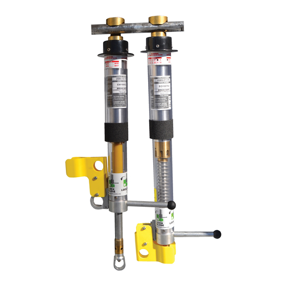
VISUAL INSPECTION
Visually inspect the tool. If any of the following are found,
remove the tool from the field and perform service:
• Soot or Dirt buildup on
components
• Damage to contacts
• Cracks of 1/4" or more on
outer tube
• Damaged Load Break Ring.
Ring should rotate freely
(shaft should NOT rotate)
• Damaged
or
discolored
Yellow Tube
2.
CONTINUITY
The Brass Contacts do not carry the load during Load
Break operation. The current path will exist inside the
tool until the load break mechanism is triggered.
A) With the tool in the CLOSED position, use a voltmeter, confirm
continuity exists between the Conductor Bar and the Conductor
Hook.
B) Confirm continuity exists while pulling the Load Break Ring
toward the open position. Continuity should exist until the load
break mechanism is engaged and the tool locks in the open
position.
C) Confirm NO continuity exists between the Conductor Bar and
the Conductor Hook when the tool is in the fully opened positioned.
3.
RESET TOOL
The BREAK-SAFE® will only reset when the Brass
Contacts are fully seated.
D
The Brass Contacts should remain seated with the tool in
the CLOSED position (F). Push the Load Break Ring up and
into the tool to ensure the Brass Contacts are fully seated. The
tool will require service and should NOT be used if the Brass
Contacts cannot be fully seated.
Phone
(828)323-8914
Fax
(828)323-8410
sales@utilitysolutionsinc.com
Email
www.utilitysolutionsinc.com
Web
101 33
Street Drive SE · Hickory, NC 28602
rd
FIELD INSPECTION PROCEDURE
BREAK-SAFE
BREAK-SAFE
• Damaged Conductor Hook
or Duckbill
• Loose Conductor Bar
• Damaged Safety Lock
• Out of Date Maintenance
Decal (maintenance
recommended every 2
years)
Exert a steady downward movement
on the Load Pick-up Trigger (D). The
Load Break Ring Assembly should
retract forcefully into the Clear Tube
Assembly. The tool should operate
firmly and smoothly.
With the tool in the Lock Close
position,
confirm
the
Contacts are fully seated (E). The
Brass Contacts will fit inside one
another so the fingers of the top
Brass Contact are touching the lip
of the lower Brass Contact.
Load Break & Pick-up Tool
®
This procedure does NOT replace or eliminate the periodic maintenance
.
®
A
B
C
E
Fully Seated
Brass
!
Carefully read and fully understand the manual prior to
operating,
operation, handling or maintenance of this device can result
in death, grievous personal injury and or equipment damage.
B-01032
USBS Field Inspection (12-17-18)
Copyright © 2018 Utility Solutions, Inc.
PATENT NO. 6,078,008 Other Patents Pending
Brass Contacts
0.25
0.25
Ω
---
Ω
F
WARNING
maintaining
or
testing
!
this
device.
Improper
Advertisement

Related Manuals for Utility Solutions BREAK-SAFE USBS-15-1


Summary of Contents for Utility Solutions BREAK-SAFE USBS-15-1
- Page 1 Contacts cannot be fully seated. Phone (828)323-8914 (828)323-8410 sales@utilitysolutionsinc.com Email B-01032 www.utilitysolutionsinc.com USBS Field Inspection (12-17-18) 101 33 Street Drive SE · Hickory, NC 28602 Copyright © 2018 Utility Solutions, Inc.
- Page 2 The Safety Lock does not RESET the tool. Refer to Inspection Procedure on reverse side and the Operation Manual for complete instructions on properly resetting the BREAK-SAFE™. Phone (828)323-8914 (828)323-8410 sales@utilitysolutionsinc.com Email B-01032 www.utilitysolutionsinc.com USBS Field Inspection (12-17-18) 101 33 Street Drive SE · Hickory, NC 28602 Copyright © 2018 Utility Solutions, Inc.