Table of Contents
Advertisement
Available languages
Available languages
Quick Links
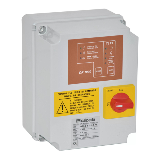
Quadro elettrico di comando 1 pompa da drenaggio con motore trifase.
Electrical control panel for 1 drainage pump with three-phase motor.
Coffret électrique de commande 1 pompe de drainage avec moteur triphasé.
Электрический пульт управления для 1 дренажного насоса с трехфазным двигателем.
QTLD 1D 12A-FA
ISTRUZIONI ORIGINALI PER L'USO
ORIGINAL OPERATING INSTRUCTIONS
INSTRUCTIONS ORIGINALES POUR L'UTILISATION
ОРИГИНАЛЬНЫЕ ИНСТРУКЦИИ ПО ЭКСПЛУАТАЦИИ
P 394.02 I
Pagina
P 394.02 GB Page
P 394.02 F
Page
P 394.02 RU ëÚ‡Ìˈ‡ 20 êÛÒÒÍËÈ
2
Italiano
8
English
14 Français
Advertisement
Table of Contents

Related Manuals for Calpeda QTLD 1D 12A-FA


Summary of Contents for Calpeda QTLD 1D 12A-FA
- Page 1 Electrical control panel for 1 drainage pump with three-phase motor. Coffret électrique de commande 1 pompe de drainage avec moteur triphasé. Электрический пульт управления для 1 дренажного насоса с трехфазным двигателем. QTLD 1D 12A-FA ISTRUZIONI ORIGINALI PER L’USO P 394.02 I...
- Page 2 Quadro elettrico di comando 1 pompa da drenaggio con motore trifase QTLD 1D 8A-FA QTLD 1D 12A-FA ISTRUZIONI PER L’USO 3. Costruzione Indice Tipi Esecuzione standard Condizioni di impiego Quadro di comando e protezione per una pompa sommergibile per drenaggio con motore trifase, Costruzione con corrente nominale di 12 A max.
- Page 3 Sul frontalino della centralina elettronica DR 1000 - con lampeggio veloce: intervento sono presenti i seguenti segnali e comandi: termoprotettore nel motore. Si spegne - Led presenza tensione. quando il termoprotettore ripristina il - Led sistema in avaria. contatto. - Led livello massimo. - acceso costantemente: intervento della - Led pompa in lavoro.
- Page 4 4. Installazione 5.2. Collegamento galleggianti 5.2.1. Collegamento a 2 galleggianti Il quadro elettrico deve essere fissato utilizzando gli appositi fori situati nella parte posteriore. Se la pompa e comandata da un galleggiante ON - Durante l’operazione installazione fare OFF, questo deve essere collegato ai morsetti 3-4. attenzione a non danneggiare le schede Il galleggiante di livello alto e allarme (facoltativo) elettroniche e gli altri componenti elettrici interni al...
- Page 5 5.4. Collegamento quadro allarme a distanza Il quadro di allarme a distanza tipo RA 100E o RA 100A deve essere collegato ai morsetti 9-10. 9 10 RA 100 6. Taratura protezione amperometrica Scheda base Centralina elettronica DR 1000 Potenziometro per la regolazione della corrente Led di protezione amperometrica Potenziometro 4.70.1086.6...
- Page 6 7. Funzionamento Attivazione funzionamento galleggianti. ATTENZIONE: quadro è settato fabbrica Il quadro esegue una prova automatica funzionamento con 2 galleggianti. di funzionamento della pompa ogni 48 Questo settaggio, al momento dell’accensione ore di inattività. provoca l’accensione del led FAILURE per circa 1 secondo.
- Page 7 Attivazione funzionamento termoprotettori con segnali esterni. Se al momento dell’accensione del quadro il led LIVELLO MASSIMO rimane spento, si deve attivare il sistema di lettura del segnale dei termoprotettori con le seguenti operazioni: - togliere l’alimentazione elettrica ruotando il sezionatore generale bloccoporta. - premere il pulsante MAN pompa e con il pulsante costantemente premuto ruotare il sezionatore generale bloccoporta e ridare...
-
Page 8: Types
Electrical control panel for 1 drainage pump with three-phase motor QTLD 1D 12A-FA OPERATING INSTRUCTIONS 3. Components Index Types Standard construction Operating conditions Control panel with protection for one submersible Components drainage pump with three-phase motor, with a 12A 3.1. DR 1000 electronic card max. - Page 9 The front of DR 1000 electronic card features the - with quick flashing: thermal contact following signals and controls: breaker intervention. It stops flashing - Power on led. when the thermal contact breaker resets - Failure led. the contact. - Maximum level led. - constantly switched on: intervention by - Pump running led.
- Page 10 4. Installation 5.2. Float switches connections 5.2.1. 2 float switches connections The electric control panel must be fastened by using the relevant holes on the back. The float switch to be connected to terminals 3-4, if the pump is controlled by ON-OFF float switch. During installation do not damage the electronic The upper level float switch and the alarm cards and the other electrical components found...
- Page 11 5.4. Control panel remote alarm The RA 100E or RA 100A type remote alarm control panel must be connected to terminals 9-10. 9 10 RA 100 6. Amperometric protection setting Base circuit board DR 1000 electronic card Potentiometer 4.70.1086.6 The intervention of the amperometric Setting the protection current of pump.
- Page 12 7. Operating Activation of the 3 float switches function The control panel is set by the manufacturer for ATTENTION: the 2 float switches functioning. This setting, at the An automatic test for pump operation is moment of switching on, causes the switching on made after 48 hours inactivity.
- Page 13 Activation of the functioning with thermal protectors with external signals. When the control panel is started and the MAX. LEVEL led is off, the reading system of the thermo protector signal must be activated with the following proceeding: - switch off the electric current by rotating the main selector switch with a door-locking device.
-
Page 14: Table Of Contents
Coffret électrique de commande 1 pompe de drainage avec moteur triphasé QTLD 1D 12A-FA MODE D’EMPLOI 3. Construction Tables des matières Types Exécution standard Conditions d’utilisation Coffret de contrôle et de protection de une pompe submersible pour drainage avec moteur triphasé... - Page 15 Sur la façade de l'unité de contrôle électronique - Clignotement rapide: intervention de la DR 1000 sont présents les commandes et voyants protection thermique du moteur. S'éteint suivants: quand le protecteur thermique rétabli le - voyant présence tension. contact. - voyant système en panne. - allumage constant: intervention de la - voyant de niveau maximum.
-
Page 16: Installation
4. Installation 5.2. Branchement flotteurs 5.2.1. Branchement de 2 flotteurs Le coffret électrique doit être fixé en utilisant les trous situés à l 'arrière. Si le pompe est commandée par un flotteur ON- Pendant l’installation, faire attention à ne pas OFF, ils doivent être connectés aux bornes 3-4. -
Page 17: Branchement Coffret Alarme À Distance
5.4. Branchement coffret alarme à distance Le coffret d'alarme à distance type RA 100E ou RA 100A doit être connecté aux bornes 9-10. 9 10 RA 100 6. Calibration protection ampèremétrique Carte de base Centrale électronique DR 1000 Potentiomètre de réglage du courant Voyant de protection ampèremétrique Voyant Potentiomètre... -
Page 18: Fonctionnement
7. Fonctionnement Activation de l'opération avec 3 flotteurs. Le coffret est réglé en d’usine pour fonctioner ATTENTION: avec 2 flotteurs. Le coffret effectue un test automatique Ce réglage, au moment de l’activation du de fonctionnement de la pompa toutes coffret, provoque l'allumage voyant... -
Page 19: Moteurs Sans Protections Thermiques
9. Coffret pour alarme à distance Activation du fonctionnement avec protections thermiques avec signaux externes. Alimentation: 220-230 V monophasé Le coffret est réglé en usine pour fontioner avec Avec: protections thermiques avec signaux externes. - Signal lumineux. Au moment de la mise en marche le voyant MAX - Signal acoustique. - Page 20 Электрический пульт управления для 1 дренажного насоса с трехфазным двигателем QTLD 1D 12A-FA àçëíêìäñàà èé ùäëèãìÄíÄñàà 3. äÓÌÒÚÛ͈Ëfl ìäÄáÄíÖãú íËÔ˚ ëڇ̉‡ÚÌÓ ËÒÔÓÎÌÂÌË Пульт управления и защита для одного ꇷӘË ÛÒÎÓ‚Ëfl дренажного погружного насоса с äÓÌÒÚÛ͈Ëfl трехфазным двигателем с макс. 3.1.
- Page 21 - короткое мигание: срабатывание ç‡ Ô‰ÌÂÈ Ô‡ÌÂÎË ˝ÎÂÍÚÓÌÌÓ„Ó ·ÎÓ͇ DR теплозащиты двигателя. Мигание 1000 ËϲÚÒfl ÒÎÂ‰Û˛˘Ë Ò˄̇Î˚ Ë ÍÓχ̉˚: прерывается, когда теплозащита - Ò‚ÂÚÓ‰ËÓ‰ ÔËÚ‡ÌËfl; восстанавливает контакт. - Ò‚ÂÚÓ‰ËÓ‰ ‡‚‡ËË ÒËÒÚÂÏ˚; - горит постоянно: срабатывание - Ò‚ÂÚÓ‰ËÓ‰ χÍÒËχθÌÓ„Ó ÛÓ‚Ìfl; защиты по току в пульте управления. - Ò‚ÂÚÓ‰ËÓ‰...
- Page 22 5.2. èÓ‰ÒÓ‰ËÌÂÌË ÔÓÔ·‚Í ов 4. ìÒÚ‡Ìӂ͇ ùÎÂÍÚ˘ÂÒÍËÈ ÔÛÎ¸Ú ÛÔ‡‚ÎÂÌËfl ‰ÓÎÊÂÌ ·˚Ú¸ 5.2.1. èÓ‰ÒÓ‰ËÌÂÌËÂ Í ÔËÍÂÔÎÂÌ Ò ÔÓÏÓ˘¸˛ ÒÔˆˇθÌ˚ı ÔÓÔ·‚Í‡Ï ÓÚ‚ÂÒÚËÈ, ‡ÒÔÓÎÓÊÂÌÌ˚ı ‚ Á‡‰ÌÂÈ ˜‡ÒÚË. èË Если насос управляется от одного поплавка ÛÒÚ‡ÌÓ‚Í ÒΉÛÂÚ ÒΉËÚ¸ Á‡ ÚÂÏ, ˜ÚÓ·˚ Ì типа ВКЛ-ВЫКЛ, поплавок...
- Page 23 5.4. èÓ‰ÒÓ‰ËÌÂÌË ‰ËÒڇ̈ËÓÌÌÓ„Ó ‡‚‡ËÈÌÓ„Ó ÔÛθڇ ÑËÒڇ̈ËÓÌÌ˚È ‡‚‡ËÈÌ˚È ÔÛÎ¸Ú RA 100E ËлË RA 100A ‰ÓÎÊÂÌ ÔÓ‰ÒÓ‰ËÌflÚ¸Òfl Í ÍÎÂÏÏ‡Ï 9-10. 9 10 RA 100 6. Калибровка защиты по току лавная схема Электронный блок DR 1000 Carte de base Centrale électronique DR 1000 Потенциометр...
- Page 24 7. ꇷÓÚ‡ ÇÍβ˜ÂÌË ̇ÒÓÒ‡ Ò 3 ÔÓÔ·‚͇ÏË. ùÎÂÍÚÓ˘ËÚ Ì‡ Á‡‚Ó‰Â-ËÁ„ÓÚÓ‚ËÚÂΠÇçàåÄçàÖ: ̇Òڇ˂‡ÂÚÒfl ̇ ‡·ÓÚÛ Ò 2 ÔÓÔ·‚͇ÏË. èË ùÎÂÍÚÓ˘ËÚ ‚˚ÔÓÎÌflÂÚ ˝ÚÓÈ Ì‡ÒÚÓÈÍ ÔË ‚Íβ˜ÂÌËË Á‡„Ó‡ÂÚÒfl ‡‚ÚÓχÚ˘ÂÒÍËÈ ÚÂÒÚ ‡·ÓÚ˚ ̇ÒÓÒ‡ Ò‚ÂÚÓ‰ËÓ‰ Ò·Ófl "FAILURE" ÔËÏÂÌÓ Ì‡ 1 ͇ʉ˚È 48 ˜‡Ò‡ ÔË ÔÓÒÚÓÂ. ÒÂÍÛ̉Û.
- Page 25 äÓ„‰‡ ÚÂÔÎÓÁ‡˘ËÚÌ˚ ÛÒÚÓÈÒÚ‚‡ ‚ Ó·ÏÓÚÍ 9. ÑËÒڇ̈ËÓÌÌ˚È ‡‚‡ËÈÌ˚È Óı·‰flÚÒfl, ̇ÒÓÒ ÒÌÓ‚‡ „ÓÚÓ‚ Í ÌÓχθÌÓÈ ÔÛÎ¸Ú ‡·ÓÚÂ. èËÚ‡ÌËÂ: 220-230 Ç ÏÓÌÓÙ‡ÁÌÓ ÇÍβ˜ÂÌË ÂÊËχ ‡·ÓÚ˚ Ò ÚÂÔÎÓÁ‡˘ËÚÓÈ äÓÏÔÎÂÍÚ‡ˆËfl: Ò Ì‡ÛÊÌÓÈ Ò˄̇ÎËÁ‡ˆËÂÈ. - Световая сигнализация Если при включении пульта светодиод - Звуковая сигнализация LIVELLO MASSIMO (МАКС.
- Page 28 P 394.02 - Con riserva di modifiche - Changes reserved - Modifications réservées - ÇÓÁÏÓÊÌ˚ ËÁÏÂÌÂÌËfl Calpeda s.p.a. - Via Roggia di Mezzo, 39 - 36050 Montorso Vicentino - Vicenza / Italia Tel. +39 0444 476476 - Fax +39 0444 476477 - E.mail: info@calpeda.it www.calpeda.it...
Need help?
Do you have a question about the QTLD 1D 12A-FA and is the answer not in the manual?
Questions and answers