Table of Contents
Advertisement
Available languages
Available languages
Quick Links
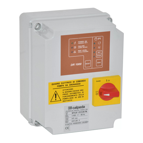
Quadro elettrico di comando 1 pompa da drenaggio con motore monofase.
Electrical control panel for 1 drainage pump with single-phase motor.
Coffret électrique de commande 1 pompe de drainage avec moteur monophasé.
Электрический пульт управления для 1 дренажных насосов с монофазным двигателем.
QMLD 1D 12A-FA
ISTRUZIONI ORIGINALI PER L'USO
ORIGINAL OPERATING INSTRUCTIONS
INSTRUCTIONS ORIGINALES POUR L'UTILISATION
ОРИГИН ЛЬНЫЕ ИНСТРУКЦИИ ПО ЭКСПЛУ Т ЦИИ
P 385.01 I
Pagina
P 385.01 GB Page
P 385.01 F
Page
P 385.01 RU ëÚ‡Ìˈ‡ 20 êÛÒÒÍËÈ
2
Italiano
8
English
14 Français
Advertisement
Table of Contents

Related Manuals for Calpeda QMLD 1D 12A-FA


Summary of Contents for Calpeda QMLD 1D 12A-FA
- Page 1 Electrical control panel for 1 drainage pump with single-phase motor. Coffret électrique de commande 1 pompe de drainage avec moteur monophasé. Электрический пульт управления для 1 дренажных насосов с монофазным двигателем. QMLD 1D 12A-FA ISTRUZIONI ORIGINALI PER L’USO P 385.01 I...
- Page 2 Quadro elettrico di comando 1 pompa da drenaggio con motore monofase QMLD 1D 12A-FA ISTRUZIONI PER L’USO 3. Costruzione Indice Esecuzione standard Tipi Quadro di comando e protezione per una pompa Condizioni di impiego sommergibile drenaggio motore Costruzione monofase, con corrente nominale di 12 A max.
- Page 3 Sul frontalino della centralina elettronica DR 1000 - con lampeggio veloce: fusibile interrotto, sono presenti i seguenti segnali e comandi: relè di potenza guasto, cavo motore - Led presenza tensione. scollegato, pompa ferma definitivamente - Led sistema in avaria. dopo i 5 tentativi di riavviamento - Led livello massimo.
- Page 4 4. Installazione 5.3. Collegamento galleggianti 5.3.1. Collegamento a 2 galleggianti Il quadro elettrico deve essere fissato utilizzando gli appositi fori situati nella parte posteriore. Se la pompa e comandata da un galleggiante ON - Durante l’operazione installazione fare OFF, questo deve essere collegato ai morsetti 3-4. attenzione a non danneggiare le schede Il galleggiante di livello alto e allarme (facoltativo) elettroniche e gli altri componenti elettrici interni al...
- Page 5 6. Taratura protezione amperometrica Centralina elettronica DR 1000 Scheda base Potenziometro per la regolazione della corrente Led di protezione amperometrica Potenziometro 4.70.1086.6 7. Funzionamento L’intervento della protezione amperometrica provoca l’arresto del ATTENZIONE: motore l’accensione Il quadro esegue una prova automatica protezione termica.
- Page 6 7.2. Funzionamento 8.1. Motori con termoprotettore galleggianti senza segnali esterni Vedere schema di collegamento galleggianti al momento dell’ paragrafo 5.3.2. accensione il led LIVELLO Il galleggiante G1 fa partire la pompa. MASSIMO rimane spento, Il galleggiante G2, posizionato più in basso, significa che il quadro è...
- Page 7 9. Quadri per allarme remoto Alimentazione: 220-230 V monofase Completo di: - Segnale luminoso. - Segnale acustico. - Led presenza tensione. - Pulsante tacitazione allarme. Segnala qualsiasi anomalia che viene a verificarsi sul gruppo pompe: - Mancanza tensione. - Gruppo in avaria (funzionamento non corretto dei galleggianti).
-
Page 8: Types
Electrical control panel for 1 drainage pump with single-phase motor QMLD 1D 12A-FA OPERATING INSTRUCTIONS 3. Components Index Types Standard construction Operating conditions Control panel with protection for one submersible Components drainage pump with single-phase motor, with a 3.1. DR 1000 electronic card 12A max. - Page 9 The front of DR 1000 electronic card features the - with quick flashing: burnt-out fuse, faulty following signals and controls: power relay, disconnected motor cable, - Power on led. after 5 tests of automatic restarting, the - Failure led. pump finally stopped caused by thermal - Maximum level led.
- Page 10 4. Installation 5.3. Float switches connections 5.3.1. 2 float switches connections The electric control panel must be fastened by using the relevant holes on the back. The float switch to be connected to terminals 3-4, if the pump is controlled by ON-OFF float switch. During installation do not damage the electronic The upper level float switch and the alarm cards and the other electrical components found...
- Page 11 6. Amperometric protection setting DR 1000 electronic card Base circuit board Potentiometer 4.70.1086.6 7. Operating The intervention of the amperometric protection causes the arrest of the motor ATTENTION: and the switching on of the thermal An automatic test for pump operation is protection LED.
- Page 12 7.2. Operating with float 8.1. Motors with thermal switches protector without external signals See the connection diagram of the float switches at paragraph 5.3.2. If the MAXIMUM LEVEL Float switch G1 starts up the pump. LED remains off at the Float switch G2, with a lower intervention level moment of starting up, it stops pump.
- Page 13 9. Control panels for remote alarm. Dimensions: 110x150x70 Power supply: 220-230 V single-phase Complete with: - Light signal - Acoustic signal - Power on led. - Alarm silence button. Signals all pump assembly malfunctions detected: - No power. - Assembly malfunction (uncorrect operating of float switches).
-
Page 14: Table Of Contents
Coffret électrique de commande 1 pompe de drainage avec moteur monophasé QMLD 1D 12A-FA MODE D’EMPLOI 3. Construction Tables des matières Exécution standard Types Coffret de contrôle et de protection d’une pompe Conditions d’utilisation submersible pour drainage avec moteur Construction monophasé... - Page 15 Sur la façade de l'unité de contrôle électronique - Clignotement rapide: fusible disjoncté, DR 1000 sont présents les commandes et voyants rupture relais de puissance, câble moteur suivants: débranché, pompe arrêtée après les cinq - voyant présence tension. tentatives redémarrage pour - voyant défauts.
-
Page 16: Installation
4. Installation 5.3. Branchement flotteurs 5.3.1. Branchement de 2 flotteurs Le coffret électrique doit être installé en utilisant les fixations situés à l 'arrière. Si la pompe est commandée par un flotteur ON- Pendant l’installation, faire attention à ne pas OFF, il doit être connecté... -
Page 17: Fonctionnement
6. Calibration protection ampèremétrique Carte de base Centrale électronique DR 1000 Potentiomètre de réglage du courant Voyant de protection ampèremétrique Voyant Potentiomètre 4.70.1086.6 7. Fonctionnement L’intervention protection ampèremétrique provoque l'arrêt du ATTENTION: moteur l'allumage voyant Le coffret effectue un test automatique protection thermique. -
Page 18: Fonctionnement Avec 2 Flotteurs
7.2. Fonctionnement avec 8.1. Moteurs avec protection flotteurs thermique sans signaux extérieurs Voir le schéma de connexion flotteurs au paragraphe 5.3.2. Avec ce réglage, au Le flotteur G1 commande le démarrage de la moment du démarrage, le pompe. voyant MAX LEVEL reste Le flotteur G2, situé... -
Page 19: Coffret Pour Alarme À Distance
9. Coffret pour alarme à distance Alimentation: 220-230 V monophasée Avec: - Signal lumineux. - Signal acoustique. - Voyant présence tension. - Bouton arrêt alarme. Signale toute anomalie se produisant sur le groupe de pompes: - Absence de tension. - Groupe en avarie (fonctionnement incorrect des flotteurs). - Page 20 Электрический пульт управления для 1 дренажного насоса с монофазным двигателем QMLD 1D 12A-FA àçëíêìäñàà èé ùäëèãìÄíÄñàà 3. äÓÌÒÚÛ͈Ëfl ìäÄáÄíÖãú ëڇ̉‡ÚÌÓ ËÒÔÓÎÌÂÌË íËÔ˚ Пульт управления и защита для одного ꇷӘË ÛÒÎÓ‚Ëfl дренажного погружного насоса с монофазным äÓÌÒÚÛ͈Ëfl двигателем с макс. номинальной силой тока...
- Page 21 - быстрое мигание: плавкий ç‡ Ô‰ÌÂÈ Ô‡ÌÂÎË ˝ÎÂÍÚÓÌÌÓ„Ó ·ÎÓ͇ DR предохранит. прерван, реле мощности 1000 ËϲÚÒfl ÒÎÂ‰Û˛˘Ë Ò˄̇Î˚ Ë ÍÓχ̉˚: неисправно, кабель двигателя - Ò‚ÂÚÓ‰ËÓ‰ ÔËÚ‡ÌËfl; отсоединен, насос окончательно - Ò‚ÂÚÓ‰ËÓ‰ ‡‚‡ËË ÒËÒÚÂÏ˚; остановлен после попыток - Ò‚ÂÚÓ‰ËÓ‰ χÍÒËχθÌÓ„Ó ÛÓ‚Ìfl; автоматич.
- Page 22 5.3. Подсоединение поплавков 4. ìÒÚ‡Ìӂ͇ 5.3.1. Подсоединение ùÎÂÍÚ˘ÂÒÍËÈ ÔÛÎ¸Ú ÛÔ‡‚ÎÂÌËfl ‰ÓÎÊÂÌ ·˚Ú¸ поплавков ÔËÍÂÔÎÂÌ Ò ÔÓÏÓ˘¸˛ ÒÔˆˇθÌ˚ı ÓÚ‚ÂÒÚËÈ, ‡ÒÔÓÎÓÊÂÌÌ˚ı ‚ Á‡‰ÌÂÈ ˜‡ÒÚË. èË Если насос управляется от одного поплавка ÛÒÚ‡ÌÓ‚Í ÒΉÛÂÚ ÒΉËÚ¸ Á‡ ÚÂÏ, ˜ÚÓ·˚ Ì типа ВКЛ-ВЫКЛ, поплавок должен Ôӂ‰ËÚ¸...
- Page 23 6. Калибровка защиты по току Centrale électronique DR 1000 Главная схема Carte de base Электронный блок DR 1000 Potentiomètre de réglage du courant Voyant de protection ampèremétrique Потенциометр для регулировки силы тока Светодиод защиты по току Potentiomètre Voyant Потенциометр Светодиод 4.70.1086.6 При...
- Page 24 8.1. Двигатели с теплозащитой 7.2. ꇷÓÚ‡ Ò 3 ÔÓÔ·‚͇ÏË без внешних сигналов ëÏÓÚË ÒıÂÏÛ ÔÓ‰ÒÓ‰ËÌÂÌËfl ÔÓÔ·‚ÍÓ‚, Ô˂‰ÂÌÌÛ˛ ‚ ‡Á‰ÂΠ5.3.2. Если при включении Поплавок G1 включает насос. светодиод МАКС. Поплавок расположенный ниже, У Р О В Е Н Ь / L I V E L L O останавливает...
- Page 25 8.2. Двигатели без теплозащиты Если двигатель не имеет теплозащиты, пульт должен быть настроен на режим работы с теплозащитой без внешних сигналов. 9. ÑËÒڇ̈ËÓÌÌ˚È ‡‚‡ËÈÌ˚È ÔÛÎ¸Ú èËÚ‡ÌËÂ: 220-230 Ç ÏÓÌÓÙ‡ÁÌÓ äÓÏÔÎÂÍÚ‡ˆËfl: - Световая сигнализация - Звуковая сигнализация - Ò‚ÂÚÓ‰ËÓ‰ ÔËÚ‡ÌËfl - ÍÌÓÔ͇ ÓÚÍβ˜ÂÌËfl Á‚ÛÍÓ‚ÓÈ Ò˄̇ÎËÁ‡ˆËË ë˄̇ÎËÁËÛÂÚ...
- Page 28 P 385.01 - Con riserva di modifiche - Changes reserved - Modifications réservées - ÇÓÁÏÓÊÌ˚ ËÁÏÂÌÂÌËfl Calpeda s.p.a. - Via Roggia di Mezzo, 39 - 36050 Montorso Vicentino - Vicenza / Italia Tel. +39 0444 476476 - Fax +39 0444 476477 - E.mail: info@calpeda.it www.calpeda.it...
Need help?
Do you have a question about the QMLD 1D 12A-FA and is the answer not in the manual?
Questions and answers