Table of Contents
Advertisement
Quick Links
User Manual UMAX140900
Version 5
Firmware 5.xx
USER MANUAL
Ethernet to CAN Converter
P/N: AX140900
In Europe:
In North America:
Axiomatic Technologies Oy
Axiomatic Technologies Corporation
Höytämöntie 6
5915 Wallace Street
33880 Lempäälä - Finland
Mississauga, ON Canada L4Z 1Z8
Tel. +358 103 375 750
Tel. 1 905 602 9270
Fax. +358 3 3595 660
Fax. 1 905 602 9279
www.axiomatic.fi
www.axiomatic.com
Advertisement
Table of Contents

Related Manuals for AXIOMATIC AX140900


Summary of Contents for AXIOMATIC AX140900
- Page 1 User Manual UMAX140900 Version 5 Firmware 5.xx USER MANUAL Ethernet to CAN Converter P/N: AX140900 In Europe: In North America: Axiomatic Technologies Oy Axiomatic Technologies Corporation Höytämöntie 6 5915 Wallace Street 33880 Lempäälä - Finland Mississauga, ON Canada L4Z 1Z8 Tel.
- Page 2 Address Resolution Protocol °C Celsius (degree) Controller Area Network Conformité Européenne (European Conformity) ® Electronic Assistant . PC application software from Axiomatic EEPROM Electrically Erasable Programmable Read-Only Memory Electromagnetic Compatibility Electrostatic Discharge Federal Communications Commission Acceleration in Gravity Units General Public License...
-
Page 3: Table Of Contents
TABLE OF CONTENTS INTRODUCTION ......................... 4 CONVERTER DESCRIPTION ..................... 5 2.1 Hardware Block Diagram ....................5 2.2 LED Indicators ......................... 6 2.3 Firmware Organization ....................6 2.3.1 Communication Device ....................7 2.3.1.1 UDP Protocol ......................7 2.3.1.2 TCP Protocol ....................... 8 2.3.2 Web Server ......................... -
Page 4: Introduction
INTRODUCTION The following user manual describes architecture, functionality and configuration parameters of the Ethernet to CAN Converter. It also contains technical specifications and installation instructions of the converter. The user should check whether the application firmware installed in the converter is covered by this user manual. -
Page 5: Converter Description
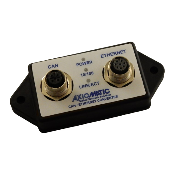
CONVERTER DESCRIPTION The Ethernet to CAN Converter is a simple device converting CAN frames into UDP or TCP IP datagrams and sending them over the Ethernet network. The device can also convert UDP or TCP datagrams into CAN frames. The converter has one CAN and one Ethernet port. It supports a high-speed CAN with baud rate up to 1Mbit/s and a fast 100Mbit/s Ethernet. -
Page 6: Led Indicators
A powerful ARM Cortex-M4 microcontroller runs IP protocol stack and all Ethernet to CAN conversion logic. 2.2 LED Indicators There are three LED indicators on the front panel of the converter. A bi-color “Power” indicator shows whether the unit is powered. It turns red when there is an error on the CAN power output. -
Page 7: Communication Device
2.3.1 Communication Device The Communication Device utilizes a proprietary communication protocol to communicate CAN messages and other auxiliary information over the Ethernet. It supports a client/server communication model. In this model, the Communication Device has a primary server role, allowing external clients to establish independent connections with the device. In addition to the server role, the device can also act as a client, if the Auto Connect to Remote configuration parameter is set to Yes. -
Page 8: Tcp Protocol
All connections with the device are virtual. On the server side, the device analyzes the incoming traffic to check for the new connections. Once a new IPAddress:Port combination is detected, the connection is established and the device starts sending CAN data with Heartbeat messages to the new node. -
Page 9: Web Server
Starting from version 5.xx, the firmware can be remotely updated through the web server. 2.3.4 Network Discovery Starting from version 5.xx, the firmware supports a proprietary Axiomatic discovery protocol. It allows to locate a converter with unknown IP address and/or web server port on a LAN using a simple Axiomatic discovery application AxioDisc.exe. -
Page 10: Converter Configuration
CONVERTER CONFIGURATION The converter supports configuration over the internal website running on the device embedded web server. The default Device IP Address is 192.168.0.34 and the default Web Server Port is 80. Please, make sure that there are no other devices on this IP address when connecting the converter for the first time to your LAN for configuration. -
Page 11: Changing Configuration Parameters
You will need to allow the site to run JavaScript (this setting is default in the majority of web browsers). If JavaScript is disabled, the website will show a message asking to activate JavaScript at the top of the web page, see Figure 6. Figure 6. - Page 12 The Save Settings button will save configuration parameters to non-volatile memory and apply the new settings. The appropriate converter subsystems will be restarted without rebooting of the whole converter. The rebooting is available from the Diagnostics screen. The Discharge Settings button will bring back the original converter settings before editing, and the Set Defaults button will load the default values of the configuration parameters into the data fields on the page.
- Page 13 Figure 9. Settings Alert. Error in Configuration Parameters The website messages should be enabled (not suppressed) in the browser to see this and other feedback messages. After pressing the Save Settings button and saving the configuration parameters, the converter replies with a confirmation message showing a result of the saving operation. For example, if the user has successfully changed the Device Port value, the following message will appear: Figure 10.
-
Page 14: Ethernet Configuration
In case the user leaves the page without saving, all changes will be discarded. The user can also discard changes by pressing the Discard Changes button. 3.2 Ethernet Configuration All Ethernet configuration parameters can be changed through the Main Settings web page, except the MAC Address, which is programmed at the factory. -
Page 15: Can Id Range Filters
Table 3. Main CAN Configuration Parameters Configuration Default Value Range Description Parameter Switched Power {Off, On} State of the switch delivering power to the CAN connector. Baud Rate 250 kbit/s {1000, 666.6(6), The CAN baud rate. 500, 250, 125, 100, 83.3(3), 50, 20, 10} Loopback {No, Yes}... -
Page 16: Can Id Mask Filters
Once the filter is activated by checking the On/Off box, the CAN input messages will pass through to the Ethernet network only if their CAN ID is within the range specified by From and To configuration parameters. ∈ [ ��������; ���� ] , ��ℎ���� ��ℎ�� �������������� ���� ����������������. ����... - Page 17 There are five independent CAN ID mask filters: Filter 1, Filter 2, …, Filter 5 available to the user. Once the filter is activated by checking the On/Off box, the CAN input messages will pass through the filter to the Ethernet network only if their CAN ID satisfies the following condition: ����...
-
Page 18: Converter Diagnostics
CONVERTER DIAGNOSTICS The user can see a real-time diagnostic information on the Diagnostics page on the converter internal website. The connection to the converter embedded web server is described in the Converter Configuration section. To see the Diagnostics page, Figure 14, the user should click on the Diagnostics link on the left side of the web page. -
Page 19: Converter Rebooting
Table 4. Health Status Health Status Condition Error Error is reported when at least one operational status is in the Error state. Warning Warning is reported when at least one operational status is in the Warning state and there are no operational statuses in the Error state. Undefined Undefined is reported when at least one operational status is in the Undefined state and there are no operational statuses in the Error or Warning state. -
Page 20: Firmware Update
Then the user selects the new firmware file using the Browse… button. The firmware file is provided by Axiomatic in a proprietary binary format with extension: .af. The file name should have the following format: AF-15129-X.XX.af, where the <X.XX> field wildcard reflects the firmware version number. -
Page 21: Applying The New Firmware
5.2 Applying the New Firmware On the Firmware Update page, the user will see the new firmware file information. Figure 18. Firmware Update Page From this point, the user can cancel the firmware update process and keep the old firmware or proceed with flashing the new firmware into the microcontroller by pressing the Apply New Firmware button. -
Page 22: Converter Deployment
AX140910, for interfacing with the converter. The SSP is downloadable from www.axiomatic.com, log-in section. The majority of Axiomatic PC software tools support the Ethernet to CAN converter. They can connect to the CAN bus using the Ethernet to CAN converter the same way as they connect to ®... -
Page 23: Converter Configuration
Ethernet to CAN Converter Ethernet cable Internet Cloud Ethernet to CAN Converter Ethernet cable Figure 21. Global Internet Connection through the WAN In the simplest scenario, two pre-configured converters can be connected by an Ethernet cable, see: Figure 22. Due to the Auto-MDIX feature, both: the straight and crossover cables can be used. -
Page 24: Client Configuration
Set Auto Connect to Remote to No to disable the client side of the converter. The Remote IP Address and Remote Port can be left untouched since they are not used by the converter when the client mode is disabled. They are grayed on the Settings page in this mode. For the CAN network, configure the necessary Baud Rate and set Loopback Messages to No. - Page 25 administrator the same way as with the server configuration. After that, the user should set the Device Port Type, Remote IP Address and Remote Port to match the settings of the converter in the server mode and activate the client mode by setting the Auto Connect to Remote to Yes. The CAN network setup is done similarly to the server mode;...
- Page 26 Please note, that if the converters are connected over the internet, the Remote IP Address of the client will be a public IP address of the server, not the internal server IP address presented as the Device IP Address on Figure 23. The network administrator on the server side will be required to configure port forwarding to open internet access to the converter in the server mode.
-
Page 27: Converter Discovery
In case the IP address and/or web server port is unknown or has been lost, the user can recover them using the Axiomatic AxioDisc.exe Windows console application. The application uses a proprietary discovery protocol and can recover IP locations of Axiomatic converters on a LAN. The AxioDisc.exe application is available upon request. -
Page 28: Technical Specifications
TECHNICAL SPECIFICATIONS 8.1 Power Supply 8.1.1 Input Power supply input is located on the Ethernet connector. The power supply uses automotive battery power. It is not compatible with the PoE (Power over Ethernet) IEEE 802.3 standard. Table 5. Power Supply Input Parameter Value Remarks... -
Page 29: Ethernet Connector
Parameter Value Remarks Internal Health Status Internal health status of the converter is Diagnostics transmitted in heartbeat messages. It is also available from the web server. 8.2.1 Ethernet Connector M12 socket, 8-pin, A-coded, female connector, Phoenix Contact, P/N: 1441817. Table 8. Ethernet Connector Pinout PIN # Description BAT + (9-36V) -
Page 30: General Specifications
EN61000-6-2:2007 8.5 Accessories Table 12. Accessories Axiomatic P/N Description AX140910 Software Support Package (SSP). Downloadable from www.axiomatic.com, log-in section. AX070531 AX070531 Ethernet and Power Cable - 1.7m (5.5 ft.), 8-pin M12 A-coded, Unterminated Leads, Ethernet Jack. AX070532 CAN Cable - 1.5 m (5 ft.), 5-pin M12 A-coded, Unterminated Leads. -
Page 31: Housing
8.6 Housing Injection molded enclosure and cover. Material: PA66, 30% glass fiber reinforced, flame retardant UL 94 V-0. Ultrasonically welded. For dimensional drawing, see Figure 27. Figure 27. Dimensional Drawing UMAX140900. Ethernet to CAN Converter. Version 5 Page: 31-35... -
Page 32: Third Party Software License Notices
THIRD PARTY SOFTWARE LICENSE NOTICES This section contains Third Party Software License Notices and/or Additional Terms and Conditions for licensed third-party software components included in the Ethernet to CAN Converter firmware. Table 13. Third Party Software License Notices Third Party Software License Notice/Terms STMicroelectronics COPYRIGHT(c) 2015 STMicroelectronics... - Page 33 *************************************************************************** FreeRTOS is distributed in the hope that it will be useful, but WITHOUT ANY WARRANTY; without even the implied warranty of MERCHANTABILITY or FITNESS FOR A PARTICULAR PURPOSE. Full license text is available on the following link: http://www.freertos.org/a00114.html LwIP v2.0.2 Copyright (c) 2001-2004 Swedish Institute of Computer Science.
-
Page 34: Version History
10 VERSION HISTORY User Firmware Manual Date Author Modifications version Version Sept. Amanda Added ISO13766-1:2018 compliance. 13, 2021 Wilkins 5.xx January Olek Added 666.6(6) kbit/s baud rate. 8, 2020 Bogush Added CAN Assistant – Visual support of the converter. 4.xx Sept 24, Olek Added Accessories subsection. - Page 35 1.xx Feb 5, Olek Initial release. 2016 Bogush UMAX140900. Ethernet to CAN Converter. Version 5 Page: 35-35...
- Page 36 • Wiring set up diagram, application and other comments as needed DC/DC Power Converters SAFE USE Engine Temperature Scanners All products should be serviced by Axiomatic. Do not open the product and perform the service yourself. Ethernet/CAN Converters, Gateways, Switches ...
Need help?
Do you have a question about the AX140900 and is the answer not in the manual?
Questions and answers