Advertisement
Quick Links
I nstallation and Com m issioning Guide
Summary
This guide discusses installation and commissioning of the WattsOn-Mark II Metering Kit. The kit
optionally includes a color touchscreen LCD. This guide addresses meter commissioning using the LCD.
The WattsOn-Mark II User Manual should be used as a supplementary guide and for commissioning
without the LCD.
This document includes the following sections:
Hardware Installation
•
•
Electrical Installation & Wiring
Commissioning
•
Color LCD
2017/07/25, rev A
Technologies Inc.
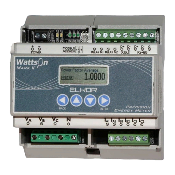
W attsOn-M ark I I M etering K it
Kit Hardware Description
Power Supply
120-240Vac input
24VDC output
15W
© Elkor Technologies Inc. 2016
Voltage
Inputs
- 1 -
6 Bainard Street
London, Ontario N6P 1A8 CANADA
tel(519)652-9959
fax(519)652-1057
Outputs
Current
Inputs
WattsOn-Mark II
Power Meter
Advertisement

Related Manuals for ELKOR WattsOn-Mark II


Summary of Contents for ELKOR WattsOn-Mark II
- Page 1 This guide discusses installation and commissioning of the WattsOn-Mark II Metering Kit. The kit optionally includes a color touchscreen LCD. This guide addresses meter commissioning using the LCD. The WattsOn-Mark II User Manual should be used as a supplementary guide and for commissioning without the LCD.
- Page 2 Hardware Physical Installation 1. The WattsOn-Mark II Metering Kit (“W2KIT”) is supplied in a polycarbonate enclosure. The only enclosure carries a NEMA 4X panel when ordered without the optional front panel LCD. 2. The enclosure includes mounting flanges. The flange dimensions are described in detail on the back of the enclosure itself.
- Page 3 Limitation of Liability Elkor Technologies Inc. (“Elkor”) reserves the right to make changes to its products and/or their specifications without notice. Elkor strongly recommends obtaining the latest version of the device specifications to assure the most current information is available to the customer. Specifications and manual are available at http://www.elkor.net...
- Page 4 LCD. While it may be used to power other equipment, it is important to consider the maximum output of the power supply (indicated on the power supply unit). The power consumption of the WattsOn-Mark II and LCD is approximately 400mA @ 24VDC. Voltage Inputs Line voltage to the voltage sensing inputs (Va, Vb, Vc) should be fused.
- Page 5 By default, the Modbus address is set to “1”. This may be easily changed via the DIP switch on the meter itself to address 1-15 (1-“F” respectively on the DIP switch). If a higher Modbus address is required, it may be set via the LCD menu (or via software). Refer to the WattsOn-Mark II User manual for more details.
- Page 6 The password may be changed via the “Password Settings” page. It is recommended to change the password so that the meter settings cannot be changed via the LCD in the future. If the password is lost, it must be recovered using a special procedure (contact Elkor for more details). Meter Settings To enter the “Meter Settings”...
- Page 7 5A Meter Type MS160 3000:1 CT Type Ratio MS240 2000:1 XYZ : 5A XYZ:5 MS360 2000:1 MSCT1, MSCT2, 7500:1 MSCT3 MSCT5 10500:1 MRS-75 7500:1 MRS-125 7500:1 MRS-2x5 7500:1 MRS-3x5 10000:1 2017/07/25, rev A - 7 - © Elkor Technologies Inc. 2016...
- Page 8 The WattsOn-Mark II allows for CT Ratio and Phase shift values on a per-channel basis, however the LCD only allows entry of the parameters on a global level. In this case, it is suggested to use the average value, since they tend to be fairly uniform among a CT model.
- Page 9 Va. The same rationale should follow for phase B and C respectively. If it is impractical to do this, Elkor provides an online “phase-swap” calculator which allows the user to simulate swapping CT phases to observe the effect.
Need help?
Do you have a question about the WattsOn-Mark II and is the answer not in the manual?
Questions and answers