Table of Contents
Advertisement
Advertisement
Table of Contents

Related Manuals for ELKOR WattsOn-Mark II


Summary of Contents for ELKOR WattsOn-Mark II
- Page 1 RECISION NERGY ETER METER USER MANUAL...
- Page 2 ELKOR TECHNOLOGIES INC. - Page 2 - WattsOn-Mark II – USER MANUAL...
-
Page 3: Installation Considerations
ALLOWS NOR AUTHORIZES ANY OTHER PERSON TO ASSUME FOR IT ANY SUCH OBLIGATION OR LIABILITY. Although the information contained in this document is believed to be accurate, Elkor assumes no responsibility for any errors which may exist in this publication. -
Page 4: Table Of Contents
9.7. Mask Write Register ............................43 9.8. Read/Write Multiple Registers .......................... 43 9.9. Diagnostic Functions ............................44 9.10. Get Comm Event Counter..........................46 9.11. Report Slave ID ............................. 46 ELKOR TECHNOLOGIES INC. - Page 4 - WattsOn-Mark II – USER MANUAL... -
Page 5: Introduction
The unit accepts up to 600V (line-to-line) directly without needing potential transformers. It may be configured for use with 333mV output CTs, mA output CTs (such as Elkor’s "safe" mA split and solid core CTs) or industry standard 5A CTs. -
Page 6: Specifications
0.15 kg (–mA and –mV models) - 0.23 kg (–5A-DL model) Mounting DIN Rail mounting 2-point screw mounting Regulatory Electromagnetic Emissions FCC part 15 Class B (residential and industrial) Safety UL 508 listed Accuracy ANSI C12.20 Class 0.2 ELKOR TECHNOLOGIES INC. - Page 6 - WattsOn-Mark II – USER MANUAL... -
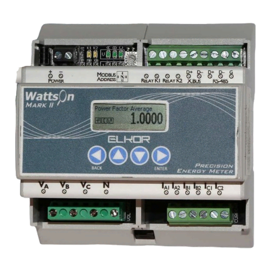
Page 7: Indicators
Green/Red Solid red indicates that Modbus is wired backwards (+ and – terminals are reversed). Indicates Elkor Expansion Bus communication. Green indicates transmission, red indicates reception. Green/Red Solid red indicates that the Expansion bus is wired backwards (+ and – terminals are reversed). -
Page 8: Installation
In some cases, the voltage may be tapped off of existing fuses or breakers. If this is not possible, Elkor recommends a 1A or lower fuse (fast acting) for protection of the installation wiring. -
Page 9: Commissioning Flowchart
0x508 and 0x509. Debug Register Read the 0x509 to test that the communications are functioning correctly. The register should read 12345 (0x3039 in hexadecimal). ELKOR TECHNOLOGIES INC. - Page 9 - WattsOn-Mark II – USER MANUAL... -
Page 10: Digital Communications
Address 0 is not a valid Modbus address; it is used for troubleshooting purposes only. See section 5.7.2, Configuring Serial Parameters (p. 28) for details on using address 0. ELKOR TECHNOLOGIES INC. - Page 10 - WattsOn-Mark II – USER MANUAL... -
Page 11: Communication
Returns the number of exception responses returned by this device since power-up. Slave Message Count 14 (0x0E) Returns the count of messages addressed to this device that were received since power-up. ELKOR TECHNOLOGIES INC. - Page 11 - WattsOn-Mark II – USER MANUAL... - Page 12 The string is null-terminated, meaning a 0 is transmitted after the last character. For example, “Elkor Technologies W2-M1-mA Hardware 1.00 Firmware 1.00”. While in bootloader mode, the string returned contains the bootloader version, for example, “Elkor Technologies Bootloader 1.00”. 4.2.4. Device ID The WattsOn implements the Read Device ID function, which provides access to various strings that identify various device properties.
-
Page 13: Register Map
Boolean True or false. False is represented by the value 0, true is represented by the value 1. ELKOR TECHNOLOGIES INC. - Page 13 - WattsOn-Mark II – USER MANUAL... -
Page 14: Instantaneous Data Registers
Voltage Phase Angle BC 0x14C 40333 ° Voltage Phase Angle AC 0x14E 40335 ° Quadrant A 0x150 40337 Quadrant B 0x152 40339 Quadrant C 0x154 40341 Sliding Window Power 0x156 40343 ELKOR TECHNOLOGIES INC. - Page 14 - WattsOn-Mark II – USER MANUAL... -
Page 15: Accumulated Data Registers
The remaining two blocks do not reflect resets, and retain their total accumulated value despite any number of resets issued by the user. Revenue-grade metering applications or applications that do not require the ability to reset the meter should always read the non-resettable registers. ELKOR TECHNOLOGIES INC. - Page 15 - WattsOn-Mark II – USER MANUAL... - Page 16 The floating-point representations of the energy registers do not use the , as they can represent arbitrarily large values. For this reason, reading the floating-point registers is recommended. However, their resolution will decrease as values grow larger. ELKOR TECHNOLOGIES INC. - Page 16 - WattsOn-Mark II – USER MANUAL...
- Page 17 Q3 Reactive Energy (Resettable) C 0x1054 44181 VARh Q4 Reactive Energy (Resettable) A 0x1056 44183 VARh Q4 Reactive Energy (Resettable) B 0x1058 44185 VARh Q4 Reactive Energy (Resettable) C 0x105A 44187 VARh ELKOR TECHNOLOGIES INC. - Page 17 - WattsOn-Mark II – USER MANUAL...
- Page 18 Q3 Reactive Energy (Resettable) C 0x1154 44437 kVARh Q4 Reactive Energy (Resettable) A 0x1156 44439 kVARh Q4 Reactive Energy (Resettable) B 0x1158 44441 kVARh Q4 Reactive Energy (Resettable) C 0x115A 44443 kVARh ELKOR TECHNOLOGIES INC. - Page 18 - WattsOn-Mark II – USER MANUAL...
- Page 19 Q3 Reactive Energy (Revenue) C 0x1254 44693 VARh Q4 Reactive Energy (Revenue) A 0x1256 44695 VARh Q4 Reactive Energy (Revenue) B 0x1258 44697 VARh Q4 Reactive Energy (Revenue) C 0x125A 44699 VARh ELKOR TECHNOLOGIES INC. - Page 19 - WattsOn-Mark II – USER MANUAL...
- Page 20 Q3 Reactive Energy (Revenue) C 0x1354 44949 kVARh Q4 Reactive Energy (Revenue) A 0x1356 44951 kVARh Q4 Reactive Energy (Revenue) B 0x1358 44953 kVARh Q4 Reactive Energy (Revenue) C 0x135A 44955 kVARh ELKOR TECHNOLOGIES INC. - Page 20 - WattsOn-Mark II – USER MANUAL...
-
Page 21: Configuration And Status Registers
0x500. Leave register 0x501 at its default value of “1”. The turn counts of various Elkor Milliamp CTs are listed in the table below. Contact Elkor for further details if the CT ratio is unknown. A correct setting of the CT ratio is critical to obtaining accurate measurements. - Page 22 * Default values depend on the input type of the device. Milliamp units default to “1”, 333 mV units default to “333”, and 5A units default to “5”. Because the primary and secondary values are equal for all models, the ratios all reduce to 1:1 regardless of the input type, by default. ELKOR TECHNOLOGIES INC. - Page 22 - WattsOn-Mark II – USER MANUAL...
- Page 23 Decimal Hexadecimal Active Power Total register 0x100 0x0001 Active Power Total register 0x100 34,464 0x86A0 Active Power Total Active Power Total register 0x101 34,464 0x86A0 register 0x101 0x0001 ELKOR TECHNOLOGIES INC. - Page 23 - WattsOn-Mark II – USER MANUAL...
- Page 24 Compatibility Mode By writing a “1” to the register, 0x525, the WattsOn-Mark II will emulate a partial register map of the legacy WattsOn-1100. The 32-bit floating-point registers from 0x300 to 0x376, as well as the configuration registers from 0x080 to 0x09E are emulated while in this mode. The 16-bit integer registers are not emulated. See the WattsOn-1100 manual for details on these registers.
- Page 25 Lagging Power Factor Leading Power Factor 270° (–) Reactive 5.6.11. Password Protection The WattsOn-Mark II features a password protection system. The device can be locked Lock Register Operation Value Unlock to prevent writes to of its registers, preventing any settings from being changed or Lock/Confirm Passcode operations (resets, reboots, etc.) to be performed.
- Page 26 1 and 65,535 seconds. Typical values are 1 minute (60 seconds), 5 minutes (300 seconds), 10 minutes (600 seconds), 15 minutes (900 seconds), 30 minutes (1800 seconds), 1 hour (3600 seconds), or any arbitrary value expressed in seconds. ELKOR TECHNOLOGIES INC. - Page 26 - WattsOn-Mark II – USER MANUAL...
- Page 27 Writes should be limited to fewer than 10,000 operations. Writes in excess of 10,000 may cause the device to become permanently read-only in order to protect itself from a flash failure. ELKOR TECHNOLOGIES INC. - Page 27 - WattsOn-Mark II – USER MANUAL...
-
Page 28: System Registers
0x602. To change the number Serial Stop Bits of stop bits, enter “1” for 1 stop bit or “2” for 2 stop bits into the register 0x603. ELKOR TECHNOLOGIES INC. - Page 28 - WattsOn-Mark II – USER MANUAL... - Page 29 2. Set the Modbus master device’s serial settings to 9600 baud, no parity, 8 data bits, and 1 stop bit. ELKOR TECHNOLOGIES INC. - Page 29 - WattsOn-Mark II – USER MANUAL...
- Page 30 7. Read any register from the WattsOn using the new settings within 3 minutes to make the change permanent. Note that the WattsOn should remain powered during this time, or its settings will revert to their previous values. ELKOR TECHNOLOGIES INC. - Page 30 - WattsOn-Mark II – USER MANUAL...
-
Page 31: Relay Output Configuration Registers
0x902/0x90C. By default, with the register set to 100, the energy accumulation registers increase by 1 for each 100 Wh/VAh/VARh of energy. Therefore, enter “1” to pulse on every 100 ELKOR TECHNOLOGIES INC. - Page 31 - WattsOn-Mark II – USER MANUAL... - Page 32 (normally closed), enter a “1” into the register. To have the relay alternate between being opened and closed each time the parameter crosses a threshold, enter a “2” into the register. ELKOR TECHNOLOGIES INC. - Page 32 - WattsOn-Mark II – USER MANUAL...
-
Page 33: Customizing The Register Map
List of register offsets of the registers that will be included in the 1 custom Modbus block. Register addresses beyond the count specified in the Size register will be ignored. Custom Block 1 Register 126 0x157F 45504 ELKOR TECHNOLOGIES INC. - Page 33 - WattsOn-Mark II – USER MANUAL... - Page 34 List of register offsets of the registers that will be included in the 4 custom Modbus block. Register addresses beyond the count specified in the Size register will be ignored. Custom Block 4 Register 126 0x187F 46272 ELKOR TECHNOLOGIES INC. - Page 34 - WattsOn-Mark II – USER MANUAL...
-
Page 35: Firmware Updates And The Bootloader
If communications is done via a PC, Elkor’s software may be used to update the device firmware. Please contact Elkor for details on the firmware update protocol if required. -
Page 36: Appendix A, Wiring Diagrams
CTs must not be used to feed multiple equipment. mV and Elkor's mA CTs do not require the use of a shorting mechanism. Their outputs are low energy, voltage limited. CT Orientation (on the conductor), CT Polarity (into the meter) and CT phasing (relationship to voltage phase) MUST be observed for correct meter operation. -
Page 37: Three-Wire (Delta) Wiring Diagram (Three Cts)
CTs must not be used to feed multiple equipment. mV and Elkor's mA CTs do not require the use of a shorting mechanism. Their outputs are low energy, voltage limited. CT Orientation (on the conductor), CT Polarity (into the meter) and CT phasing (relationship to voltage phase) MUST be observed for correct meter operation. -
Page 38: Three-Wire (Delta) Wiring Diagram (Two Cts)
CT Orientation (on the conductor), CT Polarity (into the meter) and CT phasing (relationship to voltage phase) MUST be observed for correct meter operation. System voltage and CT insulation class (typically 600V) must be observed. ELKOR TECHNOLOGIES INC. - Page 38 - WattsOn-Mark II – USER MANUAL... -
Page 39: Split-Phase Wiring Diagram
CTs must not be used to feed multiple equipment. mV and Elkor's mA CTs do not require the use of a shorting mechanism. Their outputs are low energy, voltage limited. CT Orientation (on the conductor), CT Polarity (into the meter) and CT phasing (relationship to voltage phase) MUST be observed for correct meter operation. -
Page 40: Ct Wiring Notes
We recommend using a metering Test Switch or CT Shunting Blocks to be wired between 5A CTs/PTs and WattsOn meter (ie: Elkor i-Block mV and Elkor’s mA CTs feature voltage limited outputs, and shorting mechanisms may be omitted. only ... -
Page 41: Appendix B, Modbus Protocol Details
← crc XOR d[i] loop j from 0 to 7 lsb ← crc AND 0x0001 crc ← crc LEFT-SHIFT 1 if lsb = 1 then crc ← crc XOR 0xA001 ELKOR TECHNOLOGIES INC. - Page 41 - WattsOn-Mark II – USER MANUAL... -
Page 42: Read Holding Registers
(1 byte) (2 bytes) (2 bytes) Response: Modbus Function Starting Address Register Count Address Code 1-63 0-65535 1-123 (CRC) (1 byte) (1 byte) (2 bytes) (2 bytes) (2 bytes) ELKOR TECHNOLOGIES INC. - Page 42 - WattsOn-Mark II – USER MANUAL... -
Page 43: Mask Write Register
(1 byte) (1 byte) (2 bytes) (2 bytes) Note: The response format for Read/Write Multiple Registers is identical to that of Read Holding Registers, aside from the function code. ELKOR TECHNOLOGIES INC. - Page 43 - WattsOn-Mark II – USER MANUAL... -
Page 44: Diagnostic Functions
(1 bytes) (2 bytes) (2 bytes) Response: Modbus Function Sub-function Data Address Code Code 1-63 Counter value (CRC) (1 byte) (1 byte) (1 bytes) (2 bytes) (2 bytes) ELKOR TECHNOLOGIES INC. - Page 44 - WattsOn-Mark II – USER MANUAL... - Page 45 (1 bytes) (2 bytes) (2 bytes) Response: Modbus Function Sub-function Data Address Code Code 1-63 Counter value (CRC) (1 byte) (1 byte) (1 bytes) (2 bytes) (2 bytes) ELKOR TECHNOLOGIES INC. - Page 45 - WattsOn-Mark II – USER MANUAL...
-
Page 46: Get Comm Event Counter
0 is transmitted after the last character. Example String: “Elkor Technologies W2-M1-mA Hardware 1.00 Firmware 1.00”. While in bootloader mode, the string returned contains the bootloader version, for example, “Elkor Technologies Bootloader 1.00”. The structure of its frames is as follows:... - Page 47 ELKOR TECHNOLOGIES INC. - Page 47 - WattsOn-Mark II – USER MANUAL...
- Page 48 Elkor Technologies Inc. 6 Bainard Street London, Ontario N6P 1A8 Tel: 519-652-9959 Fax: 519-652-1057 www.elkor.net © 2015, Elkor Technologies Inc.
Need help?
Do you have a question about the WattsOn-Mark II and is the answer not in the manual?
Questions and answers