Table of Contents
Advertisement
Quick Links
Advertisement
Table of Contents

Related Manuals for Scan Optics SO-5800


Summary of Contents for Scan Optics SO-5800
- Page 1 SCAN OPTICS SO-5800 MICROSCOPE USER MANUAL...
-
Page 2: Table Of Contents
SO-5800 Ophthalmic Microscope User Manual Page 2 of 31 CONTENTS INTRODUCTION ---------------------------------------------------------------------------------------------- 3 MICROSCOPE FEATURES ---------------------------------------------------------------------------------- 4 Floor stand ---------------------------------------------------------------------------------------------- 5 Pillar ---------------------------------------------------------------------------------------------------------- 6 Lower panel ---------------------------------------------------------------------------------- 6 Power supply ---------------------------------------------------------------------------------- 7 Horizontal arm ---------------------------------------------------------------------------------- 9 Pantograph arm ---------------------------------------------------------------------------------- 10... -
Page 3: Introduction
Where appropriately qualified technical personnel are identified by a user, and ratified by Scan Optics, then Scan Optics will make available on request any information which will assist in repairing the equipment. -
Page 4: Microscope Features
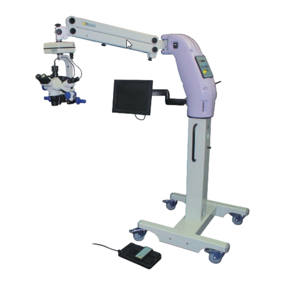
SO-5800 Ophthalmic Microscope User Manual Page 4 of 31 MICROSCOPE FEATURES Please refer to the diagram below to help you identify the main assemblies of your SO-5800 microscope. PANTOGRAPH X-Y POSITIONING UNIT HORIZONTAL MICROSCOPE HEAD ASSEMBLY POWER SUPPLY MONITOR PILLAR... -
Page 5: Floor Stand
SO-5800 Ophthalmic Microscope User Manual Page 5 of 31 FLOOR STAND The floor stand provides a stable platform for the microscope, enabling it to be moved freely and also to be locked in to position. LOCK UNLOCK To move the floor stand, first fold the pantograph arms carefully back against the horizontal arm, and lock the arms to minimise the risk of accidental damage to the microscope head. -
Page 6: Pillar
SO-5800 Ophthalmic Microscope User Manual Page 6 of 31 PILLAR The pillar contains two panels, a lower panel for connecting to mains power and the foot control, and a power supply panel for controlling microscope functions. LOWER PANEL The foot control and IEC mains plug should be connected as shown in the diagram below. -
Page 7: Power Supply
SO-5800 Ophthalmic Microscope User Manual Page 7 of 31 POWER SUPPLY The power supply controls some of the most important functions of the SO-5800 microscope. 3A CIRCUIT BREAKER MAINS SWITCH 7A CIRCUIT BREAKER STANDBY INDICATOR STANDBY BUTTON LAMP ON/OFF BUTTON... - Page 8 SO-5800 Ophthalmic Microscope User Manual Page 8 of 31 indicator will turn on) the lamp will switch off, when the button is depressed again, the lamp will return to its previous intensity setting. Speed of X-Y movement and focus/zoom movement may be controlled by rotating the control knobs clock-wise to increase speed or counter-clock-wise to decrease speed.
-
Page 9: Horizontal Arm
SO-5800 Ophthalmic Microscope User Manual Page 9 of 31 HORIZONTAL ARM The horizontal arm rotates about the top of the pillar and provides a connection interface for the main microscope power cable. Stops are fitted to prevent the arm rotating continuously around the pillar; this prevents the internal cabling from twisting. -
Page 10: Pantograph Arm
SO-5800 Ophthalmic Microscope User Manual Page 10 of 31 PANTOGRAPH ARM The pantograph arm rotates about the end of the horizontal arm and also provides a means for manually raising and lowering the microscope head. The pantograph arm includes features that enable the user to achieve the required type and feel of microscope movement. -
Page 11: Gas Spring Adjustment
SO-5800 Ophthalmic Microscope User Manual Page 11 of 31 GAS SPRING ADJUSTMENT A gas spring inside the pantograph arm provides lifting force, which is able to support the weight of the X-Y unit and microscope head at the end of the arm. -
Page 12: Safety Mechanism
Page 12 of 31 SAFETY MECHANISM The SO-5800 is fitted with a safety stop mechanism that enables the user to pre- set a particular height below which the pantograph arm will not move. Where the knob position is set closest to the horizontal arm end, there is no impediment to movement. -
Page 13: X-Y Unit
SO-5800 Ophthalmic Microscope User Manual Page 13 of 31 X-Y UNIT The X-Y unit is positioned below the rotating joint at the end of the pantograph arm. This unit allows the user to move the microscope head laterally, by means of the joystick on the foot control. - Page 14 Note that on some model SO-5800 microscopes this sensitivity is adjusted by inserting a Philips head screwdriver through a hole in the upper housing of the X-Y unit. In this case the screwdriver engages in a trim pot which may be rotated, otherwise the effect is identical.
-
Page 15: Microscope Head Assembly
SO-5800 Ophthalmic Microscope User Manual Page 15 of 31 MICROSCOPE HEAD ASSEMBLY The microscope head is suspended beneath the X-Y unit by means of a rigid bracket, which is clamped at each end. The head assembly includes viewing optics, light source and various fittings and mechanisms to aid the user in positioning the microscope. -
Page 16: Power System
SO-5800 Ophthalmic Microscope User Manual Page 16 of 31 MICROSCOPE HEAD ASSEMBLY RIGHT SIDE VIEW LAMP POWER CABLE COOLING LAMP MODULE HEAD POWER CABLE CONNECTOR BLOCK ZOOM POWER CABLE ZOOM DRIVE COVER LOCKING PIN SIDE HANDLE FOCUS DRIVE COVER POWER SYSTEM Power to the head is delivered from the X-Y unit in to a connector block, which distributes power to the various systems. -
Page 17: Focus Mechanism
SO-5800 Ophthalmic Microscope User Manual Page 17 of 31 FOCUS MECHANISM A geared dc motor provides the means for driving the head assembly up and down for focussing via foot control. The motor is located inside the focus drive cover. Focus speed may be adjusted by rotating the knob on the main power supply panel. - Page 18 SO-5800 Ophthalmic Microscope User Manual Page 18 of 31 Eyepiece caps are provided to protect dust entering the eyepiece tubes when the microscope is not in use. Simply remove the eyepieces and replace them in their protective wrapping, and insert the eyepiece caps in their place.
-
Page 19: Tilt Adjustment
HANDLES The SO-5800 is provided with two side handles and a front guide handle which enable the user to manoeuvre the microscope into position, within the limitations of the settings of the various locking knobs. The front guide handle may be removed if desired by unscrewing the socket head cap screw that fixes it to the front of the microscope head mounting bracket. -
Page 20: Video System
The SO-5800 can thus be used as a teaching microscope, or the monitor used simply to display surgery for the benefit of theatre staff. - Page 21 SO-5800 Ophthalmic Microscope User Manual Page 21 of 31 VIDEO SIGNAL CABLE WITH BNC TO RCA ADAPTER CONNECTS TO MONITOR CAMERA POWER CABLE CONNECTS TO X-Y UNIT The monitor may be tilted back or forward with friction adjustable by tightening or loosening the lower two screws on the clamping bracket.
-
Page 22: Assistant Microscope
Page 22 of 31 ASSISTANT MICROSCOPE The assistant microscope provided with the SO-5800 allows an observer to view procedures under magnification within close proximity of the operating field. In order to fit the assistant microscope, one side arm must first be removed by removing the locking pin and sliding the arm out. - Page 23 SO-5800 Ophthalmic Microscope User Manual Page 23 of 31 When the microscope is fitted to the side of the main microscope head, a tilt angle of approximately 30 degrees will enable the visual field of the assistant microscope to match that of the main microscope head. To adjust this angle, loosen the angle lock knob while holding the microscope head, tilt the head to the appropriate angle and lock it again.
- Page 24 SO-5800 Ophthalmic Microscope User Manual Page 24 of 31 UNSCREW THE MICROSCOPE LOCK KNOB LIFT THE MICROSCOPE ASSEMBLY CLEAR OF THE MICROSCOPE MOUNT TIGHTEN THE MICROSCOPE LOCK KNOB AGAIN ROTATE THE MICROSCOPE AROUND THE MOUNTING SHAFT UNTIL IT FACES THE OPPOSITE DIRECTION Issue number 2.0...
- Page 25 SO-5800 Ophthalmic Microscope User Manual Page 25 of 31 UNSCREW THE ANGLE LOCK KNOB SO THAT THE SAFETY PINS CAN BE DISENGAGED ROTATE THE MOUNTING TIGHTEN THE ANGLE LOCK KNOB AGAIN Issue number 2.0 Reference SO-5800-UM-2...
-
Page 26: Foot Control
User Manual Page 26 of 31 FOOT CONTROL The SO-5800 foot control allows the user to focus and zoom the main microscope by depressing foot switches and to move the microscope laterally by foot movement of a joystick. Note that on some models, the cable exit is from the other end of the foot control, in all other respects the functions are the same. -
Page 27: Routine Maintenance
SO-5800 Ophthalmic Microscope User Manual Page 27 of 31 ROUTINE MAINTENANCE LAMP REPLACEMENT In the event of lamp failure, the lamp may be replaced quickly and easily by removing the entire lamp module from the side of the lamp housing, and replacing it with the spare which is located behind the lower suspension bracket clamp. -
Page 28: Changing Mould Protection Pellets
Page 28 of 31 CHANGING THE MOULD PROTECTION PELLET The Scan Optics SO-5800 microscope is fitted with mould protection which lasts for approximately 3 years, but will be dependent on the storage conditions and humidity of the local environment. In extreme tropical climates it may be necessary to change the mould protection as frequently as every year. - Page 29 SO-5800 Ophthalmic Microscope User Manual Page 29 of 31 REPLACE ANTI-MOULD PELLET ZOOM ASSEMBLY BACK COVER (DETAIL OMITTED) ZOOM COVER GRUBSCREW LOCATION MOUNTING SCREW LOCATION MICROSCOPE MOUNTING BRACKET Issue number 2.0 Reference SO-5800-UM-2...
-
Page 30: Adjusting Focus Friction
Page 30 of 31 FOCUS FRICTION The SO-5800 microscope system relies on a friction device to allow the microscope head to stay in position when it is not being focussed, yet still allow the head to be focussed manually or by the motor drive. Over time or with extended use, the friction may decrease resulting in some slippage of the microscope head focussing system. - Page 31 SO-5800 Ophthalmic Microscope User Manual Page 31 of 31 FOCUS DRIVE COVER GRIP LARGE DRIVE GEAR TIGHTEN OR LOOSEN KNOB AS NECESSARY LOOSEN 2 x GRUB SCREWS RE-TIGHTEN AFTER KNOB ADJUSTED Issue number 2.0 Reference SO-5800-UM-2...
Need help?
Do you have a question about the SO-5800 and is the answer not in the manual?
Questions and answers