Advertisement
Advertisement

Subscribe to Our Youtube Channel
Related Manuals for ZF SD-10


Summary of Contents for ZF SD-10
- Page 1 SD-10/12 Description and OWNERS Manual Sept, 2011...
-
Page 2: Table Of Contents
Owners Manual SD-10 Section Introduction Gear Identification Brief description Operation Maintenance Corrosion protection... -
Page 3: I Introduction
Therefore: In respect to the handling of the transmission units the instructions stated in this manual are to be strictly followed. Maintenance programs described below are valid for the SD-10 transmission unit, not the engine. For the intervals and procedures for maintenance of the engine, refer to the operation manual and maintenance of the engine. - Page 4 I Introduction This manual includes, among other things, the following four main chapters: III Description This part briefly describes function, operation and design of the SD 10 types. IV Operation This part describes the procedures for operation and all necessary safety measures. V Maintenance This part contains all maintenance and service tasks to be performed by the operator.
-
Page 5: Gear Identification
II Gear Identification Name Plate: The name plate is fixed onto the transmission MODEL SD 10 Transmission Type iA= 2,16 Transmission ratio propeller rotation opposite engine rotation iB= 2,16 Transmission ratio propeller rotation same to a engine rotation SER. N. XXXXXXXX Transmission serial number P/N. -
Page 6: Brief Description
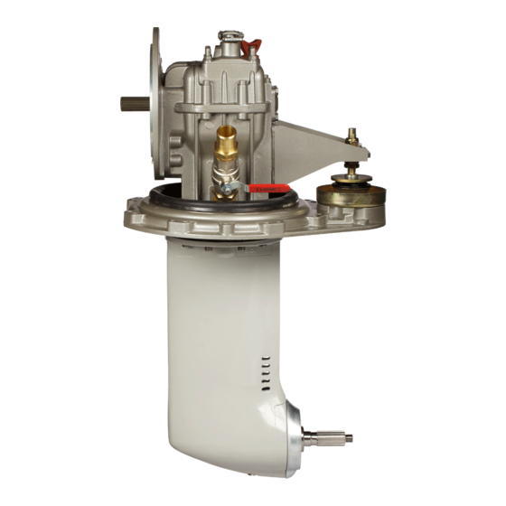
III Brief Description The ZF SD-10 Sail Drive is a reliable and well designed piece of machinery. They are of sturdy construction and utmost reliability. Nevertheless the user should make a point of observing the following instructions for installation, operation and maintenance. -
Page 7: Operation
IV Operation 1. General All SD 10 transmissions have been submitted to a test run before shipment. During normal operation, the transmission should only be shifted with the engine at idle speed. In emergency cases it is also admissible to shift at higher speeds. Visual checks for leakage should be made from time to time. - Page 8 IV Operation 2. Sailing: Boat sailing, moving in tow or anchoring. When the engine is off and the boat sails, moves in tow or is anchored, the propeller may turn with the water current. CAUTION. When the boat sails with engine switched off the shift position of the gearbox can be: 1) in neutral position and in this case the propeller is free to rotate.
- Page 9 IV Operation...
- Page 10 IV Operation 3. Gear shift operation CAUTION. Make certain that control rod or cable is easily movable. 3.1 Lever travel: see Fig. 3 Minimum travel of gear shift lever (O-A=O-B) must be 35 mm (1.3/8") for outer pivot point and 30 mm (1.3/16") for inner pivot point. 3.2 Lever position: In neutral position perpendicular to control rod or cable.
- Page 11 IV Operation...
-
Page 12: Maintenance
V MAINTENANCE Maintenance programs described below are valid for the SD-10 transmission unit, not the engine. For the intervals and procedures for maintenance of the engine, refer to the operation manual and maintenance of the engine. ROUTINE MAINTENACE... - Page 13 V OIL LEVEL CHECK 1. Check the oil level by removing the dipstick. Wipe the dipstick with a clean, lint-free cloth. 2. Insert the dipstick so that it rests on top of the threads into the case. Remove the dipstick and check the fluid level on the dipstick.
- Page 14 V MAINTENANCE SCHEDULED MAINTENANCE...
- Page 15 V OIL CHANGE Un-screw the oil dipstick. Prepare a suitable container to collect the fluid. Remove the lower plug and drain the oil. Dispose of used oil properly.
- Page 16 V OIL CHANGE Connect a hand oil pump onto the fitting of the oil drain hole in the SD-10 drive. Be careful not to damage the thread of the drain hole. Using low pressure pump, add oil. 3L -SAE 15W-40 Replace the O-rings on the oil cap Sail drive, lubricate it and prepare to reassemble it.
- Page 17 V OIL CHANGE Screw in the oil dipstick. Remove the oil pump fitting and quickly install the oil plug. Torque 10Nm. Add oil at the dipstick hole to reach the proper level as indicated on the dipstick.
- Page 18 V REMOVING PROPELLER Place a block of wood between the propeller blade and the hull. Using a 6mm Allen wrench, loosen and remove the locking screw of the bullet. Insert a suitable tool into the hole. Loosen and remove the propeller spinner nut.
- Page 19 V REMOVING PROPELLER Remove the wooden block. Remove the propeller. If necessary, use a plastic hammer and gently tap to remove. Remove the propeller sleeve.
- Page 20 V INSTALLING PROPELLER Assemble the propeller shaft thrust bearing sleeve. Install chamfered side away from propeller. Put some anti-corrosion grease on the grooves of the propeller shaft.
- Page 21 V INSTALLING PROPELLER Align the splines and insert the propeller on the propeller shaft. The propeller shaft must fit evenly on the splines. Wipe off excess grease. Install the propeller shaft nut.
- Page 22 V INSTALLING PROPELLER Place a block of wood between one of the propeller blades and the hull. Mount the special insert T2 on a suitable torque wrench and insert into the hole in the propeller nut and tighten to a torque of 125 Nm. Install the locking screw in the center.
-
Page 23: Corrosion Protection
VI CORROSION PROTECTION The SD-10 is equipped with a replaceable sacrificial anode on the lower leg of the drive. This anode is designed to dissolve in response to electrical current generated while in sea water. This anode is not designed to accommodate other hardware or other excessive electrical currents related to additional components or changes to the electrical AC and DC systems on board the vessel. - Page 24 Please keep in mind, changes made to the vessels AC and DC systems may impact the protection of the installed anode system. Damage to the SD-10 as a result of failure to maintain a good balanced galvanic protection system is not the responsibility of ZF Marine.
- Page 25 VI ANODE REPLACEMENT To minimize galvanic corrosion, the SD-10 system has a sacrificial anode placed on the foot of the sail drive. However, in particularly adverse conditions we recommend the use of additional anti- corrosion anode kit, to be installed separately.
- Page 26 VI ANODE REPLACEMENT Using a 6mm "Allen" key, remove the screws of the anode. Remove the anode of the foot. If necessary, remove using a plastic mallet.
- Page 27 VI ANODE REPLACEMENT Remove the spacer sleeve and clean any scale. Apply to the propeller shaft splines a thick layer of lubricant and/or corrosion protection material. Insert the propeller thrust sleeve onto the shaft. Place a new anode on the foot.
- Page 28 VI ANODE REPLACEMENT Tighten to a torque of 12 Nm with the cross method. Install propeller.
Need help?
Do you have a question about the SD-10 and is the answer not in the manual?
Questions and answers