Advertisement
Quick Links
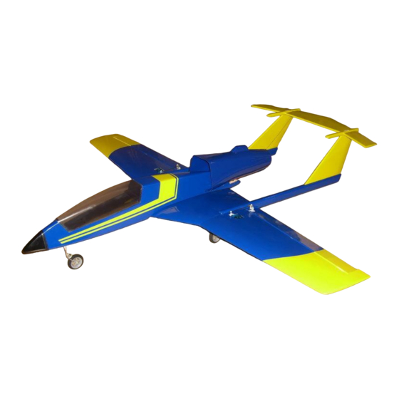
Specifications:
Construction
Span
Length
Take-off weight w/ gear
Recommended servos w/o nose-steering
Recommended fan
Recommended motor
Recommended controller
Velocity Slingjet
Balsa/foam/film
1 0 55 m m (4 1 .5 4 ")
1 0 40 m m (4 0 .9 5 ")
1050g (37oz)
3 (pcs.) + 1 for nose-wheel-steering
WM400 /70mm
Mega 16 size
Voltron ESC-60A
1
Advertisement

Related Manuals for Velocity Slingjet


Summary of Contents for Velocity Slingjet
- Page 1 Velocity Slingjet Specifications: Construction Balsa/foam/film 1 0 55 m m (4 1 .5 4 ”) Span 1 0 40 m m (4 0 .9 5 ”) Length Take-off weight w/ gear 1050g (37oz) Recommended servos w/o nose-steering 3 (pcs.) + 1 for nose-wheel-steering...
-
Page 2: Parts List
Parts List Parts List: 1. Fuselage 12. Metal parts 2. Duct Screws 3. Canopy, with magnets Collars w/set screw 4. Vertical-fin (1 pair) Pushrods (4 pcs.) 5. Stabilizer-fin (1 pair) Main landing gear 6. Vertical-fin beam (1 pair) Nose landing gear 7. - Page 3 Velocity Slingjet Tools needed to assemble this model: Scale Scissor Epoxy glue Wire-cutter CA glue Clear tape Permanent pencil Sharp hobby knife Philips screw-driver (Medium / Small) Drill Monkey wrench Caution You also need wire, to extend the servo Covering should be removed in areas wires.
- Page 4 Fuselage Pair the magnets two and two, and glue the lower magnet in place in the fuselage, and the upper magnet in the canopy with Epoxy-glue Place the canopy, over the magnets, when the epoxy-glue cures...
- Page 5 Fuselage When the epoxy-glue has cured, you have a canopy, which make a Perfekt fit to the fuselage. Trim the canopy glass, to the hatch, and fix it with canopy-glue or tape...
- Page 6 Fuselage Glue the Nose in place with CA and/or tape...
- Page 7 Tail-boom Mark area which should be uncovered on both booms, here the LH Do not cut into the wood when you cut the covering...
- Page 8 Tail-boom In the RH boom you should cut out for the servo, in center of the to tail-fin dovels Place the servo in the RH tail-boom, remenber to extend the servo-wire, and let it travel trough the boom.
- Page 9 Tail-boom Screw or glue with epoxy-glue the servo in place, and install the linkage-stopper in the servo-horn, for later rod-installation Drill a 4-5mm hole throuth the boom. Center 5mm behind wing-spar. RH and LH are equal.
- Page 10 Aileron Make a cut in center of aileron to make space for the hinge. Glue the hinge in with thick CA, or epoxy-glue...
- Page 11 Aileron Glue the hinges in place as illustrated. Glue the hinge in then wing with thick CA, or epoxy-glue, and move The aileron up and down untill the glue has cured.
- Page 12 Aileron servo-installation Cut out the aileron-servo-placement sheet, from the manual, and place it on the wing as illustarted. LH and RH are equal Cut out in the upper layer of wood, and remove foam to make space for the aileron-servo.
- Page 13 Aileron servo-installation Drill 4-5mm hole for servo-wire in the wing, aligned with the hole you made in the boom for the servo-wire. Pre-install servo, and route the RH aileron,servo wire and the tail-servo wire throuth the hole in the boom. LH is equal but with- out the tail-wire...
- Page 14 Servo-wire installation Drill 4-5mm hole for servo-wire in the outher center-part-wings, alined to the hole in the boom Drill two 4-5mm hole in the inner part of the center-part-wings. One vertical, one horisontal, for routing the wires throuth the wings upper skin.
- Page 15 Aileron servo-installation You could use the stabilizer-axle for wire-routing. Tape the wire to The axle and slide them trought the wing The wires are now routed and be ready for glueing the wing-parts together.
- Page 16 Wing Apply epoxy-glue to all parts,boom, wing-spar, both wing-parts and dowels. Hold every thing tight untill glue has cured. RH/LH is equal. Booms must be parallel Apply epoxy-glue, to both wing-parts and spar. The flat side of the Wing-spar must be up, to make the correct v-shape on the wing.
- Page 17 Aileron Cut a hole for the horn, in line with the servo-horn. Cut covering away And glue in place with epoxy. Both side equal On the lower side of the aileron press the horn-locking plate in place...
- Page 18 Aileron Drill hole in both horns, in both sides. Install the linkage-stopper, glue the nut with CA. Center the servo wih the radio, screw the servo-horn in place, and glue the servo in place the epoxy-glue. Install and the push-pull rod. (Aileron centered)
- Page 19 Tail Slide in the stabilizer axle into the stabilized. Do NOT glue it in. Make a pre-fit test, to see how long the axle must go into the Stabilizer-fins, take note of the RH one in first place.
- Page 20 Tail Glue the axle into the RH fin, with epoxy-glue Glue the fin to the RH fin-beam with epoxy-glue, remember to remove the covering in the glueing area.
- Page 21 Tail Glue the LH fin to the fin-beam, with epoxy-glue. Remember to align the axle hole to the grove. Slide in the stabilizer, and glue in the axle to the LH fin with epoxy-glue. Do not add glue to stabilizer, it must run freely. Remember the grove for the horn, must be in RH side.
- Page 22 Tail Glue the dovels half into the fin with epoxy-glue. Remove covering on fin top.
- Page 23 Tail Glue the fin and dovels to the tail-boom with epoxy-glue. Rember to angle them. Remove covering and glue in the horn with epoxy-glue. Install push-pull-rod in same way as the ailerons. Remember to center the servo...
- Page 24 Wing/Tail You will now have a complete wing with two booms, and a complete tail...
- Page 25 Cut hole in fuselage for motor-wires Install fan centered to the fuselage...
- Page 26 Install fan with to machine-screws and nuts. Install ESC in the fuselage and connect it to the motor, check for correct rotation...
- Page 27 Duct Trim duct for perfect fit to the fuselage, and fan...
- Page 28 Duct/fan Take note, that the WM400 fan have the rotor spinning at the rear. Motor in front of the fan...
- Page 29 Duct/fan Use CA and/or tape to fit the duct in place Front view. Make the duct go dupple for better stability, and the rear perfectly round. Use CA to fit...
- Page 30 Landing-gear (Not nessesary) The parts for the nose-wheel system. Except a small plastic tube. The leg is here cutted to the right length. Pre-fit holder, mark screw-holes, and drill 1,2mm holes. The hole for The leg has already been made, find it under the covering...
- Page 31 Landing-gear (Not nessesary) Screw in the nose-gear support, and install leg with collar Install the nose-gear-horn, If you want nose-wheel steering, install servo, with push-pull rod, linkage-stopper and glue the servo into the bottom of the fuselage.
- Page 32 Landing-gear (Not nessesary) Place a small tube on the leg, to make wheel/leg clearence Secure the wheel with a collar.
- Page 33 Landing-gear (Not nessesary) Make a line 10mm behind the booms starting point Place the LG over the line, and place the holders as illustrated...
- Page 34 Landing-gear (Not nessesary) Mark the screws placement, and drill 1mm holes Screw the holders in place, reinforce the holes with CA. Install wheels in same way as the nosewheel.
- Page 35 Near ready for maiden flight Install the small hard-wood spacer, and screw the wing in place. Remember to install the reciever if it should be over the wing-area. Your models shape should now look like this.
- Page 36 Near ready for maiden flight Befoce you fly: Place CG 120-135mm from leading-edge Stabilizer-travel, 8mm up/down Aileron-travel, 10mm up 6mm down Check: Ailerons, and stabilizer is running freely, and correct direction If nose-wheel-steering is installed connect it to yaw channel...
Need help?
Do you have a question about the Slingjet and is the answer not in the manual?
Questions and answers