Table of Contents
Advertisement
Quick Links
Advertisement
Table of Contents

Related Manuals for sema WPC 11+


Summary of Contents for sema WPC 11+
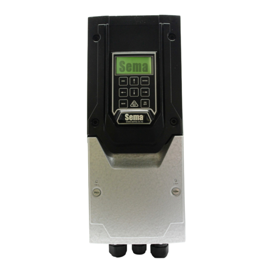
- Page 1 Water Pump Controllers 11kw and above V 2.6.4 WPC 11+...
-
Page 2: Sema Part Numbers & Contact Details
This manual applies to all Sema Water Pump Controllers above 7.5Kw Sema Part Numbers WPC3-11 11 Kw 400 Vac three phase controller c/w transducer WPC3-15 15 Kw 400 Vac three phase controller c/w transducer WPC3-22 22 Kw 400 Vac three phase controller c/w transducer The three sizes listed above are ex -stock. -
Page 3: Table Of Contents
Index Sema Part Numbers & Contact Details Installation Instructions Wiring Emergency Mode The Keypad Initial Set-Up 10-11 The Running Screen Changing Parameters 12-13 Faults Supplier Declaration of Conformity... -
Page 4: Installation Instructions
Installing Mounting The 11, 15 and 22Kw drives share the same dimensions: Please ask Sema for details on the larger units: Front Rear Side 8.00mm 14.00mm 430mm 450mm 110mm 252mm 171mm The controller must be mounted vertically with sufficient clearance above and below the drive to allow air to circulate freely. -
Page 5: Wiring
19 to 28 are not installed as they have no function. See page 8. The wiring and links shown in the picture are installed by Sema and are necessary for the correct functioning of the controller. Please do not re- move or alter any of these. - Page 6 Three Glands are fitted to the bottom of the VSD. 25mm Gland ‘25mm Gland for the Main with a brushed supply cable locknut fitted. This is meant for the motor cable 20mm Gland for the Transducer cable and the controller commu- nication cable The motor gland has a brushed locknut fitted to it (see below).
-
Page 7: Emergency Mode
Emergency Mode: If the Transducer fails the WPC will stop. This is done to prevent possible over pres- surising of the system. Because a Transducer isn’t a device which is readily available in all parts of the world an Emergency Mode has been provided to enable the unit to run from a pressure switch. To activate Emergency Mode: Turn off the power and wait until the screen is dark . - Page 8 OPTIONAL pressure selector switch (terminal 3) and the OPTIONAL remote interlock are connected here. EMERGENCY PRESSURE This terminal is used by the Sema controller as a safety shut down. Do not dis- SWITCH connect the pre-installed wire unless the transducer has failed and you wish to connect a Pressure switch to run the WPC in emergency mode.
-
Page 9: The Keypad
Setting up and Operation Using the keypad Description: The escape key functions in the same manner as the escape key on a computer it allows you to exit without sav- ing parameters and also allows you to go back a step when going through the initial setup routine. UP ARROW ... -
Page 10: Initial Set-Up
Initial Set Up A few seconds after powering the unit up for the first time, or after re-initialising it, the screen below will be displayed. The only valid key which can be pressed is the ENTER key and the only way of stopping this screen from appearing is to com- plete the setup routine. - Page 11 First Set-Point. Enter the pressure (in Bar) that you would like the system to operate at when the input connected to terminal 3 is OFF. Second Set-Point. Enter the pressure (in Bar) that you would like the system to operate at when the input con- nected to terminal 3 is ON.
-
Page 12: The Running Screen
Running The Measured Pressure The Mode The Motor RPM The Set-Point The Motor Current MODE Five different modes may be displayed here: RUNNING This is the normal mode which will be displayed when the pump is running. It also displays how long the unit has been running continuously for. - Page 13 14.) Control Method. By default this is set to ‘Ripple Control’ a Sema Ltd., invention which introduces a small pressure ripple into the pressure set-point and measures the time that it takes for the pressure to drop to determine is ther is sufficient demand for water for the pump to be kept running.
-
Page 14: Faults
If a fault occurs that stops the controller running the backlight on the screen will flash rapidly and the fault description and fault number will be displayed. Please write down this number as it will provide Sema Ltd., with important information about the cause of the fault. - Page 16 NOTES This page intentionally left blank. © Sema ltd., 2014.
Need help?
Do you have a question about the WPC 11+ and is the answer not in the manual?
Questions and answers