
Related Manuals for sema VPC3-11 Plus Mk2


Summary of Contents for sema VPC3-11 Plus Mk2
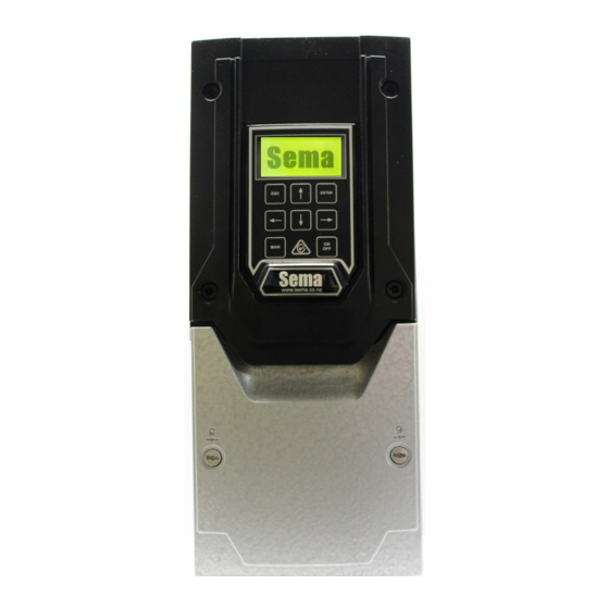
- Page 1 VPC3-11 Plus Mk2 User Manual For Mk2 Vacuum Pump Controllers 11Kw and above. V2.12.0...
-
Page 2: Sema Part Numbers & Contact Details
This manual applies to the 15 and 22kw Vacuum Pump Controllers Sema Part Numbers VPC3-11 11 Kw 400 Vac three phase controller c/w transducer and controller VPC3-15 15 Kw 400 Vac three phase controller c/w transducer and controller VPC3-22 22 Kw 400 Vac three phase controller c/w transducer and controller... -
Page 3: Table Of Contents
Index Sema Part Numbers & Contact Details Installation Instructions Wiring Recommended Practice Plant Check Control Terminals The Keypad Initial Set-Up 10-11 The Running Screen Changing Parameters 12-14 Faults Emergency Mode Supplier Declaration of Conformity Invertek Drives Manuals and Certificate of Conformity... -
Page 4: Installation Instructions
Installing Mounting The 11, 15 and 22Kw drives share the same dimensions: Front Rear Side 8.00mm 14.00mm 430mm 450mm 110mm 252mm 171mm The controller must be mounted vertically with sufficient clearance above and below the drive to allow air to circulate freely. The operating temperature range is –10 °C to 40°C. -
Page 5: Wiring
The picture above shows the control terminals of the VPC. The terminals are numbered from 1 to 28 and their functions are shown on page 8. The wiring and links shown in the picture are installed by Sema and are necessary for the correct functioning of the controller. Please do not remove or alter any of these. - Page 6 Three Glands are fitted to the bottom of the VSD. 25mm Gland 32mm Gland with for the Main a brushed locknut supply cable fitted. This is meant for the motor cable 20mm Gland for the Transducer cable and the controller commu- nication cable The motor gland has a brushed locknut fitted to it (see below).
-
Page 7: Recommended Practice
Star. There are exceptions to this with some motors supplied from overseas so please check the motors nameplate. Recommended Practice To lessen the risk of the unit being damaged by lightning strikes when it is not in use Sema recommends that the power be turned off at the completion of milking. -
Page 8: Control Terminals
Terminal Signal Control Terminal Description Number +24VDC wire from the transducer is connected here Controller The white wire from the controller communications cable is connected here No user connection No user connection No user connection 4 to 20 ma analogue The BLACK (In some cables this may be Blue) transducer wire is connected here The CLEAR (In some cables this may be a green and yellow stripe) transducer wire is connected here. -
Page 9: The Keypad
Setting up and Operation Using the keypad Description: The escape key functions in the same manner as the escape key on a computer it allows you to exit without sav- ing parameters and also allows you to go back a step when going through the initial setup routine. UP ARROW ... -
Page 10: Initial Set-Up
The default setting of “Sema Type 1” will almost always be correct but the unit can also use other types of transducer including the Delaval/John Brooks transducer. Contact Sema for advice if you are using something other than a Sema type 1 transducer. - Page 11 driven pump you can enter the speed of the pump here and then your maximum and minimum speeds will automatically refer to the pump and not the motor speeds) CONFIGURE RELAY 1: Relay 1 can be configured to operate a switched bleed solenoid. This is a specialised setting and should not be used if you are unsure of its meaning.
-
Page 12: The Running Screen
Running The Running Screen: Actual Vacuum SetPoint Mode Motor RPM Motor Current MODE Five different modes may be displayed here: MILK MODE This is the normal mode which is displayed while the unit is running HERD TEST MODE If password protected parameter number 9 (Herd Test Type) is set to anything other than “off” then pressing the manual key will switch between Milk, Herd Test and Wash modes. - Page 13 3.) Fast Decel to Stop, only use this setting if advised to by Sema Ltd., It is a specialised setting which is not suitable for the majority of installa- tions.
- Page 14 13.) INTEGRAL TIME The integral time of the control loop can be adjusted here 14.) FAST ACCEL TIME The acceleration time that the drive uses when it is near the set-point is adjusted here 15.) FAST DECEL TIME The deceleration time that the drive uses when it is near the set-point is adjusted here 16.) BLEED SOLENOID ON The optional bleed solenoid turn on RPM can be adjusted here 17.) BLEED SOLENOID OFF...
-
Page 15: Faults
If a fault occurs that stops the controller running the backlight on the screen will flash rapidly and the fault description and fault number will be displayed. Please write down this number as it will provide Sema Ltd., with important information about the cause of the fault. -
Page 17: Invertek Drives Manuals And Certificate Of Conformity
EMC Compliance The current range of Sema product is based on the Invertek Drives range of variable speed drives. Units of 7.5kw and below use the E3 series of drives and units above 7.5kw use the P2 series. Manuals and compliance information for these drives can be found at www.sema.co.nz or scan the QR codes below to be taken straight to the relevant document.
Need help?
Do you have a question about the VPC3-11 Plus Mk2 and is the answer not in the manual?
Questions and answers