
Related Manuals for sema EPCP3-11Plus Mk2


Summary of Contents for sema EPCP3-11Plus Mk2
- Page 1 EPCP3-11Plus Mk2 User Manual For Mk2 Effluent Pump Pressure Controllers 11Kw and above. V 2.6.1...
-
Page 2: Sema Part Numbers & Contact Details
This manual applies to all Sema Effluent Pump Controllers above 7.5Kw that operate by controlling the effluent pressure. Sema Part Numbers EPCP3-11 11 Kw 400 Vac three phase controller c/w transducer EPCP3-15 15 Kw 400 Vac three phase controller c/w transducer... -
Page 3: Table Of Contents
Index Sema Part Numbers & Contact Details Installation Instructions Wiring Emergency Mode The Keypad Initial Set-Up 10-11 The Running Screen Changing Parameters 12-14 Faults Supplier Declaration of Conformity Invertek drives manuals and declarations of conformity Please read the important information below: Thanks very much for purchasing one of our effluent pump controllers. -
Page 4: Installation Instructions
Installing Mounting The 11, 15 and 22Kw drives share the same dimensions: Please ask Sema for details on the larger units: Front Rear Side 8.00mm 14.00mm 430mm 450mm 110mm 252mm 171mm The controller must be mounted vertically with sufficient clearance above and below the drive to allow air to circulate freely. -
Page 5: Wiring
The picture above shows the control terminals of the EPCP. The terminals are numbered from 1 to 28 and their functions are shown on page 8. The wiring and links shown in the picture are installed by Sema and are necessary for the correct functioning of the controller. Please do not remove or alter any of these. - Page 6 Three Glands are fitted to the bottom of the VSD. 25mm Gland ‘25mm gland for for the Main the motor cable. supply cable This gland has a ‘brushed locknut’ fitted. To termi- nate the screen on the motor ca- ble simply bare 10 20mm Gland for the to 15mm of the Transducer cable, the...
-
Page 7: Emergency Mode
Emergency Mode: If the Transducer fails the EPCP will stop. This is done to prevent possible over pres- surising of the system. Because a Transducer isn’t a device which is readily available in all parts of the world an Emergency Mode has been provided to enable the unit to run from a pressure switch. To activate Emergency Mode: Turn off the power and wait until the screen is dark . - Page 8 The white wire from the controller communications cable is connected here Remote Run As supplied by Sema there is a link between terminals 1 and 3. A remote stop switch may be connected in place of this. No user connection...
-
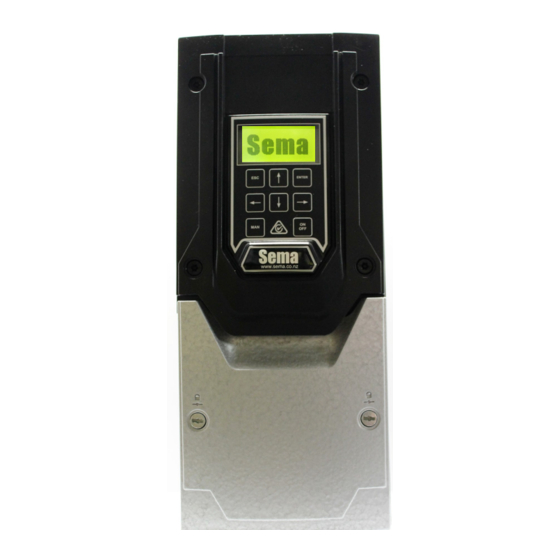
Page 9: The Keypad
Setting up and Operation Using the keypad Description: The escape key functions in the same manner as the escape key on a computer it allows you to exit without sav- ing parameters and also allows you to go back a step when going through the initial setup routine. UP ARROW ... -
Page 10: Initial Set-Up
Initial Set Up A few seconds after powering the unit up for the first time, or after re-initialising it, the screen below will be displayed. The only valid key which can be pressed is the ENTER key and the only way of stopping this screen from appearing is to com- plete the setup routine. - Page 11 First Set-Point. Enter the pressure (in Bar) that you would like the system to operate at when the inputs connected to terminals 27 and 28 are OFF. Second Set-Point. Enter the pressure (in Bar) that you would like the system to operate at when the input con- nected to terminal 27 is ON.
-
Page 12: The Running Screen
Running The Running Screen: Actual Pressure Mode Motor RPM SetPoint Motor Current MODE Six different modes may be displayed here: STOPPED If the on/off button is pressed this will be displayed. RUNNING When the pump is running this will be displayed followed by a time showing how long it has been running for. - Page 13 Non Password Protected Parameters: 0.) Password The password is Enter the password here which unlocks the protected parameters (11 to 19) 00004 1.) Minimum Speed The minimum speed of the pump can be adjusted here. 2.) Maximum Speed The maximum speed of the pump can be adjusted here. 3.) Setpoint 1 This is the pressure set-point when inputs 27 &...
- Page 14 14.) Control Method. By default this is set to ‘Conventional’. Ripple control is a Sema Ltd., invention which intro- duces a small pressure ripple into the pressure set-point and measures the time that it takes for the pressure to drop to deter- mine is there is sufficient flow for the pump to be kept running.
-
Page 15: Faults
If a fault occurs that stops the controller running the backlight on the screen will flash rapidly and the fault description and fault number will be displayed. Please write down this number as it will provide Sema Ltd., with important information about the cause of the fault. -
Page 17: Invertek Drives Manuals And Declarations Of Conformity
EMC Compliance The current range of Sema product is based on the Invertek Drives range of variable speed drives. Units of 7.5kw and below use the E3 series of drives and units above 7.5kw use the P2 series. Manuals and compliance information for these drives can be found at www.sema.co.nz or scan the QR codes below to be taken straight to the relevant document.
Need help?
Do you have a question about the EPCP3-11Plus Mk2 and is the answer not in the manual?
Questions and answers