
Related Manuals for FTS DTS-12


Summary of Contents for FTS DTS-12
- Page 1 EXTREME ENVIRONMENTS. EXTREMELY RELIABLE. DTS-12 SDI Turbidity Sensor User Manual 1.800.548.4264 | www.ftsinc.com 700-DTS-12 Rev. 28 16 Apr 2020...
- Page 2 Contact Information Canadian Headquarters: 1065 Henry Eng Place Victoria, BC | V9B 6B2 | Canada www.ftsinc.com Toll-free: 1.800.548.4264 Local: 250.478.5561 Technical support portal: http://support.ftsinc.com Email: service@ftsinc.com...
-
Page 3: Table Of Contents
SDI-12 COMMANDS..................19 Notation for SDI-12 Commands ................... 19 3.1.1 General SDI-12 Commands 3.1.2 SDI-12 Measurement and Request Data Commands SDI-12 Commands for DTS-12 ver 20 or later ............21 3.2.1 Measurement Command Table(ver 20 and later) 3.2.2 Request Data Commands... - Page 4 3.2.3 Extended (X) Commands SDI COMMANDS FOR DTS-12 (ver 19 or earlier) ............23 3.3.1 SDI-12 Measurement Commands 3.3.2 Extended (C) Commands (ver 19 and earlier) Appendix A TECHNICAL SPECIFICATIONS ..............26 Appendix B ORDERING AND UPGRADE INFORMATION ..........27...
-
Page 5: Chapter 1 Operation
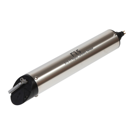
DTS-12 is 0 to 1600 NTU, making it ideal for stream and river applications. The DTS-12 has a built-in wiper that is useful for reducing the effects of silt build up and biological fouling of the sensor optics. The DTS-12 is factory programmed with turbidity calibration coefficients. -
Page 6: Unpacking
DTS-12 turbidity readings; however, if a shaded site is not available, if possible, mount a shade to eliminate sunlight effects on the DTS-12. The installation directions (Section 1.4) contain further details on how to optimally deploy the DTS-12 to avoid interference from sunlight. -
Page 7: Installation
The DTS-12 must be oriented such that the optical window has at least 4 inches axial end clearance and 2 inches radial side clearance from any physical objects (e.g. the river bottom or protective pipe). -
Page 8: Sdi Connection
Figure 1-4: Typical DTS-12 Installation using FTS DTS-12 Deployment Guide SDI Connection The SDI cable (nominally 25 feet long) may be connected to the DTS-12 by waterproof gland or underwater connector. Normally the free end of the cable is shipped with a length of the polyurethane jacket removed to expose the three 20 AWG conductors. -
Page 9: Sdi-12 Connectorized Cable
SDI-12 connectorized cable The DTS-12 can be ordered with fixed length connectorized cables (60 and 100 ft.) that allow for quick disconnect and re-connection. This watertight connection is submersible and permits sensor removal from a field installation without removing the cable. In complex installations or on installations with long cable runs this is a very desirable attribute. - Page 10 One of the male prongs on the DTS-12 end cap has a larger diameter than the other two. This larger diameter prong must be aligned with the two reference nipples on the cable connector (as shown in the connection photos) to ensure that the prongs are inserted into the correct receptacles.
- Page 11 This inappropriate handling WILL damage the female receptacles inside the Cable Connection. For proper technique, see the FTS video at https://www.youtube.com/watch?v=mG Tighten the locking sleeve to complete the connection D3ECbYVpw&feature=player embedded...
-
Page 12: Cable Connection And Disconnection (V2)
1.6.2 Cable Connection and Disconnection (V2) When connecting/disconnecting the V2 cable, care must be taken not to damage the DTS-12’s pins. Always pull/push the cable straight on/off and avoid bending and twisting the cable during connection and disconnection. The DTS-12 will be shipped with a protective cap and the pins will be coated with di-electric grease. -
Page 13: Operation
Operation When power is first applied to the DTS-12 a wipe cycle will occur. This is a normal part of the sensor initialization. When the wiper returns to its normal parked position the DTS-12 is ready to accept SDI commands. -
Page 14: Address Configuration
If the wiper blade edge appears ragged or uneven then it should be replaced. Ensure you are working in a clean, dry area. Each DTS-12 is shipped with a spare piece of wiper material packaged in a small zip-lock bag attached to the cable. If additional replacement parts are needed, refer to Section 1.10 700-DTS-12 Rev. - Page 15 Feed the new wiper blade onto the wiper arm through the distal slot. Figure 1-11: Replacing the wiper blade 3. Clean the thumbscrew threads of residual Loctite using the isopropyl alcohol and toothbrush. 700-DTS-12 Rev. 28 - 16 Apr 2020 Page 11/28...
-
Page 16: Replacing The Wiper Blade Assembly
1.11 Replacement Parts If replacement parts are required, the entire wiper can be ordered from FTS by specifying part number DTS12-WIPER. If individual components are required, specify the part number according to the table below. -
Page 17: Chapter 2 Quick Start Guide
Chapter 2 QUICK START GUIDE This chapter will take you through the steps to set up the DTS-12 to an Axiom Datalogger. It is meant as a quick reference. Detailed instructions can be found in the Axiom Operator’s Manual. Connect the DTS-12 sensor cable to the Datalogger on one of the orange SDI ports. In order for the sensor to start providing data to the Datalogger it must be: 1. -
Page 18: Mapping The Sensor
If any of the defined or detected fields remain red, then mapping must be conducted. Mapping the Sensor Scroll down the Detected column to view the detected DTS-12 (which will be defined as NEW). Figure 2-4: DTS-12 defined as NEW Press on the red Vendor/Serial field of the detected sensor. -
Page 19: Configuring The Dts-12
The next screen will display the icons of the sensors which have been defined. Note that if the Datalogger has already been configured for the DTS-12 (by loading a Configuration file, or replacing a DTS-12 for example) the SDI DTS-12 icon will be displayed Figure 2-8: Sensor page showing defined sensors 700-DTS-12 Rev. -
Page 20: Setting Up Logging - In-Line Logging Enabled
If the SDI DTS-12 icon does not appear, it must be added. To add the DTS-12, select the Add icon, then press on the SDI Generic icon. Figure 2-9: Adding the DTS-12 The DTS-12 Setup screen will be displayed. Select Edit then press on the blue M2 bar (M Command). -
Page 21: Setting Up Logging - Regular Logging
Regular logging provides the user the ability to create more complex logging than that offered by the In-line Logging option. From the Home page, select the Data icon and then the Setup Cog. Figure 2-12: Regular Logging 700-DTS-12 Rev. 28 - 16 Apr 2020 Page 17/28... - Page 22 Logged Variables column. Continue to add variables. Figure 2-14: Logging Interval Setup Screen Once done, select OK and the new Logging interval will be displayed in the Logging Interval page. Return to the Home page. 700-DTS-12 Rev. 28 - 16 Apr 2020 Page 18/28...
-
Page 23: Chapter 3 Sdi-12 Commands
Italic command (except Address Query). Valid values 0-9, a-z, A-Z. The DTS-12 uses the standard SDI -12 Commands and protocols which makes it compatible for use with DCP’s or transmitters. Note the following: the “a” in each command should be replaced with the sensor address number •... -
Page 24: Sdi-12 Measurement And Request Data Commands
The data is read using a subsequent Request Data command (aD0!). The DTS-12 version 12 and later can measure in one of two modes. The sensor will arrive in the factory default mode of median. To change the mode to mean, refer to section 3.2.3, Extended Commands. -
Page 25: Sdi-12 Commands For Dts-12 Ver 20 Or Later
The format of a C command and retrieval of the data is the same as for M commands. SDI-12 Commands for DTS-12 ver 20 or later This section lists the SDI-12 commands recognized by the DTS-12 ver 20 or later. For DTS-12 version 19 or earlier, refer to Section 3.3. IMPORTANT:... -
Page 26: Measurement Command Table(Ver 20 And Later)
If additional data needs to be read, then an aD1! command is sent, then and etc., up to as required to retrieve all data. aD2! aD9! Example Measurement Command followed by a Request Data Command: 700-DTS-12 Rev. 28 - 16 Apr 2020 Page 22/28... -
Page 27: Extended (X) Commands
Report low temperature wipe aX g ce! y=enabled cutoff status n=disabled SDI COMMANDS FOR DTS-12 (ver 19 or earlier) This appendix lists the SDI-12 commands recognized by the DTS-12 version 19 and earlier. 700-DTS-12 Rev. 28 - 16 Apr 2020 Page 23/28... -
Page 28: Sdi-12 Measurement Commands
To determine your version number perform an Identification Command (aI!). Identification response = aCN#FTS----DTS12—VX-SN#. The VX field is the version. See Section 3.2 for SDI Commands for DTS-12 with version numbers 20 or later. 3.3.1 SDI-12 Measurement Commands Command Measures... -
Page 29: Extended (C) Commands (Ver 19 And Earlier)
Version 11 or higher Enable low temperature aC81! Will not wipe below cutoff. wipe cutoff Version 11 or higher Disable low temperature aC82! Attempts wipe regardless of temp wipe cutoff Version 11 or higher 700-DTS-12 Rev. 28 - 16 Apr 2020 Page 25/28... -
Page 30: Technical Specifications
+12 V DC (nominal range: 9.6 V – 16 V) Standby current 0.35 mA Active current 50 mA Wiping motor current 200 mA Weight 604g Length 30.48 cm Diameter 5.08 cm 700-DTS-12 Rev. 28 - 16 Apr 2020 Page 26/28... -
Page 31: Appendix Bordering And Upgrade Information
As of Aug 1, 2020, all newly purchased quick-connect DTS-12 turbidity sensors (DTS-12) will ship with the V2 DTS-12 end cap and will require V2 cables. There is no impact to previously purchased DTS-12 turbidity sensors (DTS-12) as these can be updated with a new endcap for use with the new cables. -
Page 32: Document Revision History
Added installation pictures. Updated information on DTS-12-DG. Information on installation of DTS-12-DG removed to new 13 Sep 2018 document 700-DTS-12-DG (DTS-12 Deployment Guide Installation Instructions). 16 Apr 2020 Corrected X commands (DTS-12), updated with V2 cable connector 700-DTS-12 Rev. 28 - 16 Apr 2020 Page 28/28...
Need help?
Do you have a question about the DTS-12 and is the answer not in the manual?
Questions and answers