
Related Manuals for FTS THS-3


Summary of Contents for FTS THS-3
- Page 1 THS-3 Temperature and Humidity Sensor Installation and Quick Setup Guide 1.800.548.4264 www.ftsenvironmental.com 700-THS3 Rev. 6 – 05 May 2015...
-
Page 2: Contact Information
Contact information 1065 Henry Eng Place Victoria, B.C., V9B 6B2 CANADA www.ftsenvironmental.com Toll-free 1-800-548-4264 Local 250-478-5561 Technical support http://support.ftsenvironmental.com 1.800.548.4264 www.ftsenvironmental.com 700-THS3 Rev. 6 – 05 May 2015... -
Page 3: Table Of Contents
General ..................................5 Tower Mounting ..............................5 Maintenance ................................7 Chapter 3 Sensor Quick Setup Guide ...................... 9 Configuring the THS-3 ............................9 In-line Logging ..............................11 Regular Logging ..............................11 Confirm Sensor Operation ..........................13 Changing the Setup ............................14 Document Revision History .......................... -
Page 4: Chapter 1 Introduction
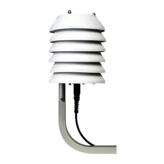
Chapter 1 Introduction General Description The THS-3 is a combined analog Temperature and Relative Humidity sensor. Temperature is sensed by an encapsulated thermistor housed in a stainless steel tube. Thermistor contacts are brought directly to the sensor connector for easy temperature measurement. Relative Humidity is measured using a capacitive-type humidity transducer. -
Page 5: Specifications
Temperature Ground (thermistor -) others No Connect Table 1: THS Sensor Signal Connections Specifications The specifications for the THS-3 Temperature and Humidity Sensor are shown in Table 2. Operating Temperature: -40 to 60°C Operating Humidity: 0 to 100% RH General Operating Voltage: 9.6 to 20 Vdc, 12 V nominal... -
Page 6: Chapter 2 Installation And Maintenance
Ensure you review local regulations prior to installation. In the United States the THS-3 Temperature & Humidity sensor is to be installed on the south side of the mast 4 to 8 feet above ground. The Canadian regulations are to install the sensor on the south side of the mast 1 to 1.3 meters above the ground. - Page 7 Temperature and Humidity Sensor Figure 2-1: Attaching the assembly to the support arm 2. Loosely attach the support arm to the mast or tower with the clamp bolts at the desired sensor height. Ensure the support arm’s “V” is fitted to the pole. Figure 2-2: U-Bolt assembly and support arm attachment Page 6/15 700-THS3 Rev.
-
Page 8: Maintenance
Maintenance FTS recommends that the sensor be returned to FTS for a yearly check of the THS-3 sensor’s calibration. Also, FTS recommends that during any site visit a visual check of the THS-3 cable, connector and sensor filter is performed. - Page 9 Temperature and Humidity Sensor 2.3.1 Inspecting and Replacing the Filter To inspect the THS-3 filter, you must first remove the sensor from the housing assembly. a) Remove any cable ties which will prevent the sensor from being removed from the housing being careful not to damage the cable b) Use a 5/8”...
-
Page 10: Sensor Quick Setup Guide
After installation, the sensor should be given a minimum of thirty minutes to acclimatize to a site before data is taken. Configuring the THS-3 Connect the THS-3 to the data logger on the red Temperature and Humidity port. From the data logger’s home page, select the Sensors icon. Figure 3-1: Home Page The next screen (SDI Sensor Mapping) will display the icons of the dedicated sensors which are already added and set up. - Page 11 Temperature and Humidity Sensor The Air Sensor Setup screen will be displayed: Figure 3-3: Edit the fields by pressing on the field box: Sensor: The default name for the sensor is THS. You can change this if desired. Active: This box must be checked in order for the sensor to collect data Temp: This is the air temperature.
-
Page 12: In-Line Logging
Temperature and Humidity Sensor In-line Logging In order to view and collect data on a variable, it must be logged. In-line Logging provides the user an option to set up simplified Logging and add variables to Current Conditions from the Sensor Setup screen . - Page 13 Temperature and Humidity Sensor Figure 3-5: Regular Logging The Logging intervals screen will be displayed. If there are already logging intervals set up they will be seen here. Logging intervals created through the Data functions, as described here, are displayed in blue. Logging intervals created using the In-line Logging feature are displayed in green. Figure 3-6: Logging Intervals Press the Add icon, then the Edit icon.
-
Page 14: Confirm Sensor Operation
Return to the Home page. Confirm Sensor Operation Now that the THS-3 is setup, confirm its operation and ensure data is being logged. From the Home page select the Data icon to display the Data Status screen. Then select the Table icon. -
Page 15: Changing The Setup
Temperature and Humidity Sensor Figure 3-9: WindSonic Data Return to the Home page. Changing the Setup If you want to change the setup, from the Home page select the blue Sensors icon, then select the THS icon. Select the Set up Cog which will bring you to the THS Sensor Setup page. -
Page 16: Document Revision History
Temperature and Humidity Sensor Document Revision History Revision Date Description 27 Jul, 2006 Original release 2 Oct, 2006 Updated specifications. 25 Jan, 2007 Added special order specification. 11 Oct, 2007 Updated for new filter, updated specifications. 27 Apr, 2015 Format change. Updated pictures. Added Quick Setup Guide. 5 May, 2015 Minor corrections Page 15/15...
Need help?
Do you have a question about the THS-3 and is the answer not in the manual?
Questions and answers